2N® SmartCom PRO - Input circuits
2N® SmartCom PRO is equipped with three inputs, which are mutually galvanically connected with the GND reference point (have a common GROUND).
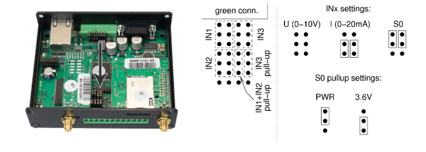
The input circuits can work in three modes – voltage, current or logical levels – as configured.
- disconnect 2N® SmartCom PRO from the power supply before opening the cover
- loosen the screws and open the box lid to get access to the PCB jumpers.
The figures below show the location of the current/voltage/S0 switching jumpers:
Note: If you want to use voltage mode and current mode properly, you need to calibrate 10-bits A/D converter connected to the input terminals (IN1, IN2, IN3). But keep in mind that an uncalibrated input is still functional (but can read values less precisely).
Input calibration is described in manual - section 3.4
Voltage Measurement
Voltage can be measured in the range between 0 and 10 V DC. Make sure that the 2N® SmartCom PRO jumpers are set as shown in the figure above before using this mode.
Current Measurement
Electric current can be measured in the range between 4 and 20 mA. Make sure that the 2N® SmartCom PRO jumpers are set as shown in the figure above before using this mode
An example is given for the ADC circuit 1 (scadc1). To read circuit 2(3), replace 1 with 2(3) in the command (scadc2/scdc3).
at^scadc1="get_value"
- The command performs measurement on the selected interface and sends the calibrated value measured.
at^scadc1="adc_value"
- The command performs measurement and returns the value from the A/D converter.
at^scadc1="calib_min"
- Automatic interface calibration according to the currently measured value.
at^scadc1="calib_max"
- Automatic interface calibration according to the currently measured value.
at^scadc1="threshold_low",1200
- Manual calibration setting (minimum values). Setting options: 0–4090.
at^scadc1="threshold_high",3250
- Manual calibration setting (maximum values). Setting options: 0–4090.
at^scadc1="save"
- The command saves the changes.
Logical Level Monitoring
You can monitor the logical levels of voltage and current signals. Use other commands than those intended for classic measurements and define the threshold levels. Again, use the AT commands for reading values on input circuits.
at^scdin1="get_value"
- The command detects the logical level on the selected interface and sends the value 1/0
at^scdin1="calib_min"
- Automatic interface calibration according to the currently measured value
at^scdin1="calib_max"
- Automatic interface calibration according to the currently measured value
at^scdin1="threshold_low",1400
- Manual calibration setting (minimum values). Setting options: 0–4090
at^scdin1="threshold_high",3450
- Manual calibration setting (maximum values). Setting options: 0–4090
at^scdin1="save"
- The command saves the changes.