3. Events
Automation defines the following types of events:
- AudioLoopTest – audio test performed
- CallSessionStateChanged – calling session state changed
- CallStateChanged – call state changed
- CardEntered – RFID card entered
- CardHeld – RFID card held
- CodeEntered – numeric code entered
- Counter – Event Course Count (events)
- Delay – delay defined
- DoorOpenTooLong – excessively long door opening
- DtmfEntered – DTMF numeric code detected in call
- DtmfPressed – DTMF code received in call
- ErrorStateChanged – error state changed (for 2N LiftIP 2.0 only)
- FingerEntered – fingerprint reader authentication
- FlexiTrigger – command received to start from the display's own GUI
- HttpTrigger – HTTP/HTTPS command received
- InputChanged – digital input changed
- KeyPressed – key pressed
- KeyReleased – key released
- LicensePlateRecognized – license plate recognition
- MobKeyEntered – Bluetooth reader authentication
- MotionDetected – motion detected by the camera
- MulticastTrigger – command for multiple devices received
- OnvifVirtualOutputChanged – event received from VMS
- NoiseDetected – noise detected by the microphone
- RegistrationStateChanged – SIP account registration state changed
- Rebooted – device start/restart detected
- RescueTerminated – rescue mode terminated (for 2N LiftIP 2.0 only)
- ProfileStateChanged – time profile start/stop
- ScreenChanged – switch from/to Showcase mode / Idle mode
- SilentAlarm – silent alarm activated
- Time – specific time (alarm clock)
- Timer – periodical event timer
- UnauthorizedDoorOpen – unauthorized door opening
- UserAuthorized – user authorization
- OutputChanged – output changed
- SwitchChanged – output event
See below for details on the events and their Input parameters and use.
AudioLoopTest
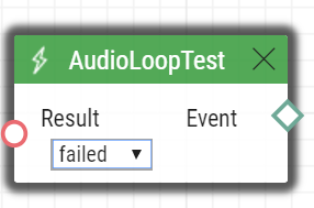
The AudioLoopTest block defines the event generated after the loudspeaker and microphone test (Audio Loop Test) is performed. The subsequent actions are executed based on the test result.
Input parameters
- Result – this parameter specifies the required test result.
Valid values:
- any – the event is generated whenever the test is performed (regardless of the result).
- passed – the event is generated whenever the test is successful.
- failed – the event is generated whenever the test fails.
The parameter is optional, the default value is failed.
Output parameters
- Event – the Event output to invoke the connected Event or Action.
Example
An event generated after the audio loop test if the test result is negative (i.e. the microphone or loudspeaker is out of order):
 |
CallSessionStateChanged
The CallSessionStateChanged block defines the event generated by a call session state change (ringing, connection, call termination, etc.). One call session can include multiple calls. For example, when a phone number in a group with a contact deputy is called, two parallel calls are set up to two different destinations.
Input parameters
- State – define the call session state change. The state changes whenever the call state is changed. The terminated call state does not occur until all individual calls within a call session have been terminated.
- Valid values:
- connecting – call setup in progress
ringing – ringing start
connected – successful call connection
terminated – call session termination
- Valid values:
- Direction – define the call direction.
- Valid values:
incoming – incoming calls
outgoing – outgoing calls
any – both directions.
- The parameter is optional, the default value is any.
- Valid values:
Output parameters
- Event – the Event output to invoke the connected Event or Action.
- State – the detected call state which generated this event. The options correspond to the State parameter.
- Direction – the detected call direction which generated this event. The options are incoming or outgoing.
Example
Event generated by the termination of an outgoing call:
 |
CallStateChanged
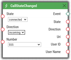
The CallStateChanged block defines a state change of every call in a call session.
Input parameters
- State – define the call state change.
- Valid values:
- connecting – call setup in progress
ringing – ringing start
connected – successful call connection
terminated – call termination.
- Valid values:
- Direction – define the call direction.
- Valid values:
incoming – incoming calls
outgoing – outgoing calls
any – both directions.
- The parameter is optional, the default value is any.
- Valid values:
- Number – define the identifier (phone number, IP address) to be matched against the caller's identifier to make the event happen. Enter multiple comma-separated numbers if necessary. A non-completed value is the same as any.
- This parameter is optional, the default value is any.
Output parameters
- Event – the Event output to invoke the connected Event or Action.
- State – the detected call state which generated this event. The options correspond to the State parameter.
- Direction – the detected call direction which generated this event. The options are incoming or outgoing.
- Uri – the output containing the opponent's complete SIP uri.
- User ID – user identification that generated this event.
- User Name – user name that generated this event.
Example
Event generated whenever an incoming call is connected to number 555:
 |
CardEntered
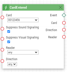
The CardEntered block defines the event generated by tapping (swiping) of the RFID card with the defined ID (for RFID card reader models only).
Input parameters
- Card – define the RFID card ID; refer to the Card Reader subsection in the Configuration Manual.
- Valid values:
valid – any valid card (included in the intercom card list)
invalid – any invalid card
- any – any valid or invalid card
- < > (empty value) – the event will not be generated
- Or, complete the card ID manually (multiple comma-separated items can be entered).
- Valid values:
- Suppress Visual Signaling – suppress visual signaling (LED, toast messages on display) initiated by detection of an invalid card. The parameter is optional.
- Valid values:
disabled – signaling is not suppressed
enabled – signaling is suppressed (default value)
- Valid values:
- Suppress Sound Signaling – suppress sound signaling initiated by detection of an invalid card. The parameter is optional.
- Valid values:
disabled – signaling is not suppressed
enabled – signaling is suppressed (default value)
- Valid values:
Reader – define the card reader / module to be used
- Valid values:
- internal_cardreader – internal card reader (2N ® IP Vario, Force)
- external_cardreader – external card reader (2N IP Vario, Force)
- any – any reader / module
- Or, complete the module name manually as configured in the Module Name parameter in the Hardware / Extenders / Modules / Used module menu (2N IP Verso).
- The parameter is optional, the default value is any.
- Valid values:
- Direction – define direction
- Valid values:
- in – reader with defined incoming direction
- out – reader with defined outgoing direction
- any – both directions
- The parameter is optional, the default value is any.
- Valid values:
Output parameters
- Event – the Event output to invoke the connected Event or Action.
- Card – ID of the detected card which was the last to generate this event.
- Direction – configured direction at the card reader (in, out, any).
- Reader – name of the module which was used (internal_cardreader, external_cardreader, <module_name>).
Example
Event generated by entering of the card with ID 00123456:
 |
CardHeld
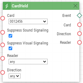
The CardHeld block defines the event generated by holding of the RFID card with the defined ID (for RFID card reader models only). The event is generated by holding the RFID card for 4s at the RFID card reader.
Input parameters
- Card – define the RFID card ID; refer to the Card Reader subsection in the Configuration Manual.
- Valid values:
valid – any valid card (included in the intercom card list)
invalid – any invalid card
- any – any valid or invalid card
- < > (empty value) – the event will not be generated
- Or, complete the card ID manually (multiple comma-separated items can be entered).
- Valid values:
- Suppress Visual Signaling – suppress visual signaling (LED, toast messages on display) initiated by detection of an invalid card. The parameter is optional.
- Valid values:
disabled – signaling is not suppressed
enabled – signaling is suppressed (default value)
- Valid values:
- Suppress Sound Signaling – suppress sound signaling initiated by detection of an invalid card. The parameter is optional.
- Valid values:
disabled – signaling is not suppressed
enabled – signaling is suppressed (default value)
- Valid values:
- SuppressTones – suppress audio and video signaling initiated by detection of an invalid card. The parameter is optional.
- Valid values:
disabled – signaling is not suppressed
enabled – signaling is suppressed (default value)
- Valid values:
- Reader – define used card reader / module
- Valid values:
- internal_cardreader – internal card reader (2N IP Vario, Force)
- external_cardreader – external card reader (2N IP Vario, Force)
- any – any reader / module
- Or, complete the module name manually as configured in the Module Name parameter in the Hardware / Extenders / Modules / Used module menu (2N IP Verso).
- The parameter is optional, the default value is any.
- Valid values:
- Direction – define direction
- Valid values:
- in – reader with defined incoming direction
- out – reader with defined outgoing direction
- any – both directions
- The parameter is optional, the default value is any.
- Valid values:
Output parameters
- Event – the Event output to invoke the connected Event or Action.
- Card – ID of the detected card which was the last to generate this event.
- Reader – name of the module which was used (internal_cardreader, external_cardreader, <module_name>).
- Direction – configured direction at the card reader (In, Out, Unspecified).
Example
Event generated by holding of the card with ID 0012456:
 |
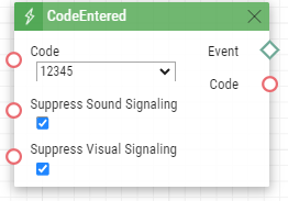
CodeEntered
The CodeEntered block defines the event generated by entering of a numeric code and confirmation with the * key (for numeric keypad models only).
Input parameters
- Code – define the numeric code.
- Valid values:
numeric code – 12345, e.g. (multiple comma-separated items can be entered)
valid – any valid code
invalid – any invalid code
- any – any valid or invalid code
- < > (empty value) – the event will not be generated
- Valid values:
- Suppress Visual Signaling – suppress visual signaling (LED, toast messages on display) initiated by receiving of an invalid numeric cod. The parameter is optional.
- Valid values:
disabled – signaling is not suppressed
enabled – signaling is suppressed (default value)
- Valid values:
- Suppress Sound Signaling – suppress sound signaling initiated by receiving of an invalid numeric cod The parameter is optional.
- Valid values:
disabled – signaling is not suppressed
enabled – signaling is suppressed (default value)
- Valid values:
Output parameters
- Event – the Event output to invoke the connected Event or Action.
- Code – the received numeric code which was the last to generate this event.
Example
Event generated by entering code 12345* on a keypad:
 |
Counter
The Counter block monitors the count of courses of the previous defined events. The event courses input as Increase increase the monitored count. The event courses input as Decrease decrease the monitored count. The decrease events need not be set. The block can generate an out event or action either every time the event/action occurs or after the count reaches/exceeds the value defined in Max Value.
Input parameters
- If, during the automatic function, any of the input parameters of this block is changed, the monitored count automatically returns to the Min Value.
- Increase – define the event whose course increases the count.
- Decrease – define the event whose course decreases the count. This parameter is optional.
- Reset – define the event after which the monitored count returns to the Min Value.
- Condition – define the condition to be met in order the change of the monitored count can be applied (Increase, Decrease, Reset). This parameter is optional.
- Mode – define the event generating method.
- Valid values:
- always (default) – the block generates an event whenever the monitored count changes.
- condition – the block generates an event whenever the monitored count reaches or exceeds the Max Value.
- Valid values:
- Min Value – define the starting value of the count to be monitored. This is the lowest possible value that the Decrease event cannot decrease.
- Max Value – define the maximum value of the count to be monitored. See Auto Reset for more details.
- Valid values: Remember that the Max Value must be higher than the Min Value!
- Step – define the monitored count increase/decrease step.
- Valid values: positive numbers (> 0)
- Auto Reset – define that the monitored count automatically returns to the original Min Value when the Max Value is reached or exceeded. If Auto Reset is not activated and the Max Value has been reached/exceeded, the increasing of the course count value will be suspended (i.e. the Increase events are ignored).
Output parameters
- Event – Event/Action generating output. The output is activated whenever the Max Value is reached/exceeded (condition mode) or whenever any of the input events is detected (always mode).
- Value – current count of the monitored courses.
Upozornění
- Remember that the Min Value must be lower than the Max Value (Min Value < Max Value).
- It is advisable that the Min Value, Max Value and Step values are set in such a manner that the difference between the Max Value and Min Value is an integer multiple of the Step value.
Example
-TBS-
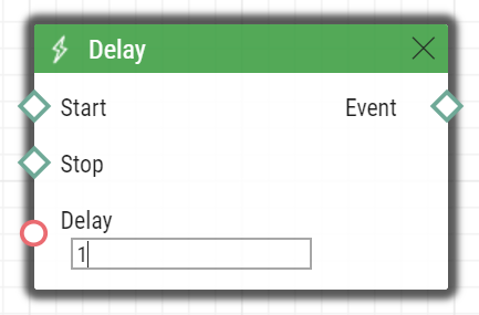
Delay
The Delay block defines the event generated with a defined delay after another specified event. Define this event to delay the response to the other event by a defined time interval (Delay).
Input parameters
- Start – define the event that starts the delay.
- Stop – define the event that stops the delay. The parameter is optional.
- Delay – define the delay time. It is only possible to enter a numerical value, not a value from an output parameter produced by other events.
- Example of valid values:
- 10 – 10 seconds (units are unnecessary)
- 10s – 10 seconds
- 100ms – 100 milliseconds.
Output parameters
- Event – the Event output to invoke the connected Event or Action.
Example
Event generated 1s after the rise of event on row 1:
 |
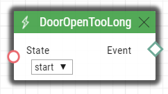
DoorOpenTooLong
The DoorOpenTooLong block defines the event generated in case the door stays open longer than as set.
Input parameters
- State – state of the door sensor that generates the event.
- Start – event start
- End – event end
- Valid values:
Output parameters
- Event – output for generating of the assigned Event or Action.
Example
The DoorOpen event is longer than set.
 |
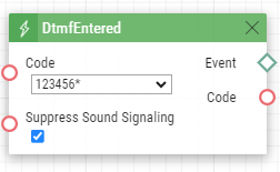
DtmfEntered
The DtmfEntered block defines the event that is generated by entering of a numeric code confirmed with the * key in DTMF in an incoming or outgoing call.
Input parameters
- Code – define the numeric code.
- Valid values:
numeric code – 12345, e.g. (multiple comma-separated items can be entered)
valid – any valid code
invalid – any invalid code
- any – any valid or invalid code
- < > (empty value) – the event will not be generated
- Valid values:
- Suppress Sound Signaling – suppress sound signaling initiated by receiving of an invalid numeric code. The parameter is optional.
- Valid values:
disabled – signaling is not suppressed
enabled – signaling is suppressed (default value)
- Valid values:
Output parameters
- Event – the Event output to invoke the connected Event or Action.
- Code – the detected received numeric code which was the last to generate this event.
Example
The event generated upon detection of DTMF code 123456*.
 |
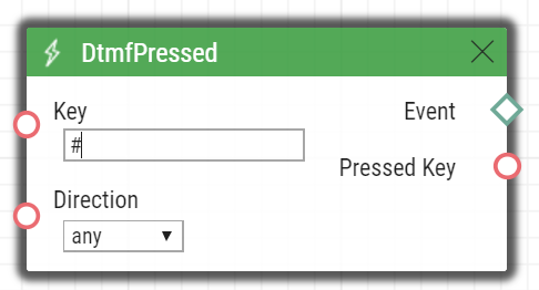
DtmfPressed
The DtmfPressed block defines the event that is generated when the defined or any DTMF code is received from the defined group. DTMF codes are detected both in incoming and outgoing calls.
Input parameters
- Key – define the DTMF code (or DTMF code group). If this parameter is not completed, the event is generated whenever any DTMF code is detected (default value: Any).
- Valid values:
- 0, 1, 2, 3, 4, 5, 6, 7, 8, 9, *, #, A, B, C, D
- any for any key (default value).
- Separate the values with a comma to specify a group of codes.
- Direction – define the call direction.
- Valid values:
incoming – incoming calls
outgoing – outgoing calls
any – both directions
- The parameter is optional, the default value is any.
- Valid values:
Output parameters
- Event – the Event output to invoke the connected Event or Action.
Pressed Key – the recorded received DTMF code which was the last to generate the event. The DTMF is stored in the Key parameter format.
Example
Event generated upon detection of DTMF code #:
 |
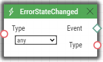
ErrorStateChanged
The ErrorStateChanged block defines the event generated by various error states of 2N LiftIP 2.0 changing.
Input parameters
- Type – select which type of event will trigger this block.
- Valid values:
- any – any of the types below
button-error – ALARM1 error
Note
- A button error is indicated whenever the button is activated longer than as set in Hardware > Digital inputs in the web configuration interface of the device.
- button-fixed – ALARM1 error end
- audio-error – last audio test yielded an audio error.
- audio-fixed – audio error was fixed during the last audio test.
- Valid values:
Output parameters
- Event – output for generating of the assigned Event or Action.
- Type – type of the event that triggered this block.
Example
Event generated by the ALARM1 error / ALARM1 error fixed, or audio error / audio error fixed detection.
 |
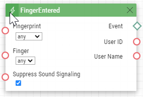
FingerEntered
The FingerEntered block defines the event generated by identifying a known fingerprint on the fingerprint reader (for fingerprint reader equipped devices only).
Input parameters
- Fingerprint - define validity of the entered fingerprint.
- Valid values:
- valid – the fingerprint belongs to a user
- invalid – the fingerprint is unknown
- any – any entered fingerprint
- Valid values:
Finger – define one of two fingerprints stored for the user.
- Valid values:
- any – any fingerprint of the user
- F1 – the fingerprint was defined as "F1" for Automation at the Fingerprint enrolment
- F2 – a fingerprint was defined as "F2" for Automation at the Fingerprint enrolment
- Valid values:
- Suppress Sound Signaling – suppress sound signaling initiated by detection of an invalid user (fingerprint). The parameter is optional.
- Valid values:
disabled – signaling is not suppressed
enabled – signaling is suppressed (default value)
- Valid values:
Output parameters
- Event – the Event output to invoke the connected Event or Action.
- User ID – user identification that generated this event.
- User Name – user name that generated this event.
Example
An event generated by valid entering of a fingerprint on a biometric reader.
 |
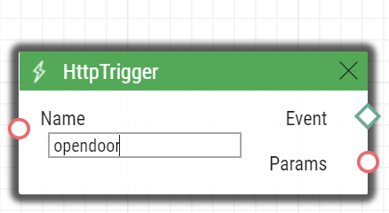
HttpTrigger
The HttpTrigger block defines the event generated by receiving of an HTTP/HTTPS command from the intercom HTTP/HTTPS server. When the HTTP/HTTPS command https://ip_addr/api/automation/trigger?triggerId=id is received, the event will be generated whose ID matches the value that follows 'trigger/' in the HTTP/HTTPS command. The intercom sends a simple reply to this request (200 OK).
Remember to enable Automation API and have an account with access to automation in Services > HTTP API to send HTTP/HTTPS commands.
Input parameters
- Name – define a unique HTTP/HTTPS command identifier including alphabetical characters and digits.
Output parameters
- Event – the Event output to invoke the connected Event or Action.
- Params – parameters sent in the SendHttpRequest block or the command coming to the 2N IP intercom.
The HttpTrigger event is always generated by the HTTP/HTTPS command which can carry a list of user Input parameters as included in the URI command.
http://ip_address/api/automation/trigger?triggerId=id¶m1=value1¶m2=value2
The list of Input parameters follows the ? character. Each parameter must include the name and value separated with the = character. If the list includes more Input parameters than one, & is used as the separator.
The HTTP/HTTPS-received Input parameters are available as HttpTrigger block Output parameters. The output parameters name equals to the name of the parameter transferred - $(line.param1) a $(line.param2).
Example
Event generated by receiving of the following HTTP/HTTPS command: https://ip_address/api/automation/trigger?triggerId=opendoor :
 |
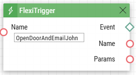
FlexiTrigger
The FlexiTrigger block defines the event generated when a command to start automation is received from the device display. Automations can be triggered from the display's own graphical user interface via the Automation Trigger action.
Input parameters
- Name – specifies the unique identifier of the Automation Trigger that triggers the automation.It can contain alphabetic characters and digits.The value of the Name parameter is created by the user when setting the action on the custom GUI page in Flexi Builder (see the configuration manual).
Output parameters
- Event – the Event output to invoke the connected Event or Action.
Example
Event generated by running the OpenDoorAndEmailJohn action on the device display. An action with this name must be preconfigured in the display's own GUI.
 |
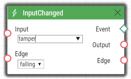
InputChanged
The InputChanged block defines the event generated by a change of the logic level on the defined digital input.
Input parameters
- Input – define the logic input.
- Valid values:
tamper – tamper switch input
input1 – digital input 1
input2 – digital input 2
cr_input1 – digital input 1 on card reader
cr_input2 – digital input 2 on card reader
- There may be different lists of valid values for different 2N IP intercom models; refer to the Available Digital Inputs and Outputs subsection.
- Valid values:
- Edge – define the detected change on the digital input.
- Valid values:
falling – falling edge, change from log. 1 to log. 0
rising – rising edge, change from log. 0 to log. 1
- The parameter is optional, the default value is rising.
- Valid values:
Output parameters
- Event – the Event output to invoke the connected Event or Action.
- Output – the detected ID of the input whose change was the last to generate this event. The options correspond to the Input parameter values.
- Edge – the detected edge change which was the last to generate this event. The options are falling or rising.
Example
Event generated by disconnection of the tamper switch (device opening):
 |
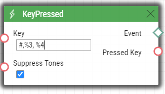
KeyPressed
The KeyPressed block defines the event generated by pressing of the defined key or any key from the defined group.
Input parameters
- Key – define the key or a key group. If this parameter is not completed, the event is generated upon pressing of any key (default value: any).
- Valid values:
0, 1, 2, 3, 4, 5, 6, 7, 8, 9, *, # for numeric keypad buttons
%1, %2, .., %999 for quick dial buttons
- T – for display touch
- B – for Bluetooth authentication initializing key
alarm1 – for lift products (ALARM1 contact)
alarm2 – for lift products (ALARM2 contact)
vas_top – for lift products (upper Voice Alarm Station contact)
vas_bottom – for lift products (lower Voice Alarm Station contact)
any for any button (default value)
- Separate the values with a comma while defining more keys than one.
- Valid values:
- SuppressTones – suppress audio and video signaling initiated by pressing of a non-programmed quick dial button. The parameter is optional.
- Valid values:
disabled – signaling is not suppressed
enabled – signaling is suppressed (default value)
- Valid values:
Output parameters
- Event – the Event output to invoke the the connected Event or Action.
- Pressed Key – the recorded code of the key which was the last to generate this event. The key code is stored in the Key parameter format.
Example
Event generated by pressing of # and quick dial button 3 or 4:
 |
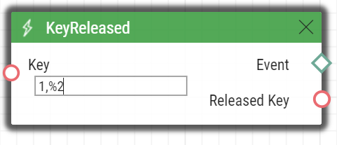
KeyReleased
The KeyReleased block defines the event generated by releasing of the defined pressed key or any key from the defined group.
Note
- Vario model: the event is generated whenever the button is pressed, the functionality is the same as with KeyReleased.
Input parameters
- Key – define the key or a key group. If this parameter is not completed, the event is generated upon releasing of any key (default value: any).
- Valid values:
0, 1, 2, 3, 4, 5, 6, 7, 8, 9, *, # for numeric keypad buttons
%1, %2, .., %999 for quick dial buttons
alarm1 – for lift products (ALARM1 contact)
alarm2 – for lift products (ALARM2 contact)
vas_top – for lift products (upper Voice Alarm Station contact)
vas_bottom – for lift products (lower Voice Alarm Station contact)
- any for any button (default value).
- Separate the values with a comma while defining more keys than one.
- Valid values:
Output parameters
- Event – the Event output to invoke the connected Event or Action.
- Released Key – the recorded code of the key which was the last to generate this event. The key code is stored in the Key parameter format.
Example
Event generated by releasing of 1 and quick dial button 2:
 |
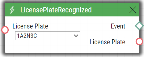
LicensePlateRecognized
The LicensePlateRecognized block defines the event generated by a license plate recognized HTTP request receiving.
Input Parameters
- License Plate – define the license plate.
- Valid values:
- license plate – specific license plate text
- valid – any valid license plate
- invalid – any invalid license plate
- any – any valid or invalid license plate
- Valid values:
Output Parameters
- Event – Event/Action generating output
- License Plate – license plate text
Example
An event generated by reading license plate 1A2N3C.
 |
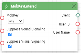
MobKeyEntered
The MobkeyEntered block defines the event generated by reading a known WaveKey on the Bluetooth reader (for the devices with Bluetooth reader only).
Input parameters
- MobKey – define the current WaveKey validity.
- Valid values:
- valid – the WaveKey belongs to a user
- invalid – the WaveKey is unknown
- any – any entered WaveKey
- Valid values:
- Suppress Visual Signaling – suppress visual signaling (LED, toast messages on display) initiated by detection of an invalid user (WaveKey). The parameter is optional.
- Valid values:
disabled – signaling is not suppressed
enabled – signaling is suppressed (default value)
- Valid values:
- Suppress Sound Signaling – suppress sound signaling initiated by detection of an invalid user (WaveKey). The parameter is optional.
- Valid values:
disabled – signaling is not suppressed
enabled – signaling is suppressed (default value)
- Valid values:
Output parameters
- Event – the Event output to invoke the connected Event or Action.
- User ID – user identification that generated this event.
- User Name – user name that generated this event.
Example
 |
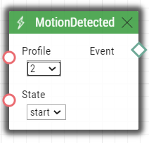
MotionDetected
The MotionDetected block defines the event generated at motion detection. Motion can be detected by the internal camera only. The Motion detection Input parameters are configured in the Hardware / Camera / Internal Camera menu, section Motion Detection Settings.
Input parameters
- Profile – define the motion detection profile to which this event shall respond.
- Valid values:
- any – motion detected by any of the motion detection profiles
- 1 – motion detected by motion detection profile 1
- 2 – motion detected by motion detection profile 2.
- Valid values:
- State – define whether the motion start or end should be detected.
- Valid values:
- start – start of the motion
- end – end of the motion
The parameter is optional, the default value is start.
- Valid values:
Output parameters
- Event – the Event output to invoke the connected Event or Action.
Example
An event generated whenever motion starts being detected by motion detection profile 2.
 |
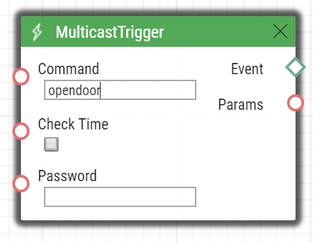
MulticastTrigger
The MulticastTrigger block defines the event generated by receiving of a command sent via SendMulticastRequest. The request is a message sent by UDP to a multicast address (235.255.255.250:4433) and can thus be received by multiple devices at the same time. The message includes the command ID (Command parameter) and additional optional Input parameters. The message can be password-secured (Password parameter).
Input parameters
- Command – define the command ID to distinguish the command types. The MulticastTrigger block responds to the SendMulticastRequest action only if the command identifier is the same. Any text containing the A–Z, a–z and 0–9 characters can be used for identification. The Upper/Lower case must be respected in the command name.
- CheckTime – enable/disable the check of the command receiving time against the time value included in the command message to eliminate attacks caused by repeating of an already processed message. Synchronized time (via the NTP server) on all command sending and receiving devices is required for this function.
- Valid values:
- disabled – message time is not checked
- enabled – message time is checked (enhanced security).
- The parameter is optional, the default value is 0.
- Valid values:
- Password – define the password to secure the command against unauthorized access. The password must match the value defined in the SendMulticastRequest action to which MulticastTrigger is expected to respond.
Output parameters
- Event – the Event output to invoke the connected Event or Action.
- Params – parameters sent in the SendMulticastRequest Action.
The MulticastTrigger event is generated whenever a mass command including the list of user Input parameters (Params parameter, MulticastRequest action) is received. Each of the Input parameters has a user-defined unique name and is available as an Output parameter of the same name in the MulticastTrigger block.
Example: Suppose a mass command generated by the MulticastRequest action is received, in which Params=“AAA=123” is included. The MulticastTrigger event which processes this command will automatically include value 123 for the AAA output parameter. This output parameter can be referred to in the interconnected blocks.
Example
Event generated by receiving of a mass opendoor command:
 |
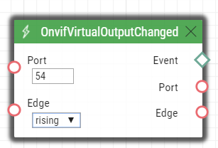
OnvifVirtualOutputChanged
The OnvifVirtualOutputChanged block helps transmit events from VMS to a 2N IP intercom.
Input parameters
- Port – set the port to set VMS. Valid values: 50–54.
- Edge – define the change detected on the virtual input.
- Valid values:
- falling – falling edge, change from log 1 to log 0
- rising – rising edge, change from log 0 to log 1
- The parameter is optional, the default value is rising.
- Valid values:
Output parameters
- Event – Event/Action generating output.
- Port – port value changed from VMS. Valid values: 50–54.
- Edge – the last virtual input change that generated this event. Valid values: falling or rising.
Example
The event generated when the virtual port value changes.
 |
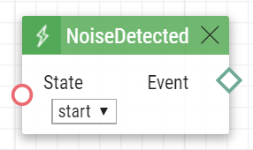
NoiseDetected
The NoiseDetected block defines the event generated at noise detection. Noise can be detected by the internal microphone only. The noise detection Input parameters are configured in the Hardware / Audio menu, section Noise Detection Settings.
Input parameters
- State – define whether the noise start or end should be detected.
- Valid values:
- start – start of the noise
- end – end of the noise
The parameter is optional, the default value is start.
- Valid values:
Output parameters
- Event – the Event output to invoke the connected Event or Action.
Example
Event generated at the start of the noise.
 |
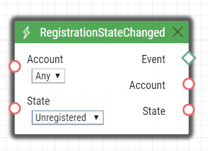
RegistrationStateChanged
The RegistrationStateChanged block defines the event generated at a SIP account registration state change. Set the SIP registration in Services > SIP. Registration gets changed whenever the intercom is switched on, configuration is changed or registrar connection gets lost, for example.
Input parameters
- Account Type – select the account type for which events are to be monitored.
- Valid values:
- general – general purpose SIP accounts (e.g., SIP2)
- msteams – dedicated SIP account for MS Teams integration
- any – any account
- The parameter is optional, the default value is any.
- Valid values:
- Account – select the account for which events are to be monitored.
- Valid values:
- 1 – account 1
- 2 – account 2
- 3 – account 3
- 4 – account 4
- any – any account
- The parameter is optional, the default value is any.
- Valid values:
- State – set the registration state that generates the event.
- Unregistered – intercom not registered
- Registering – registration in progress
- Registered – intercom is registered
- Unregistering – unregistration in progress
- Any – any state change
- Valid values:
- The parameter is optional, the default value is Any.
Output parameters
- Event – the Event output to invoke the connected Event or Action.
- Account – select the account for which events are to be monitored.
- State – set the registration state that generates the event.
Example
Event generated when the intercom has been unregistered (whenever the registrar failed to respond to a periodical registration request):
 |
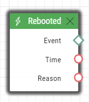
Rebooted
The Rebooted block defines the event generated in case the device is started/restarted.
Input parameters
This block has no Input parameters.
Output parameters
- Event – output for generating of the assigned Event or Action.
- Time – device start/restart time.
- Reason – reboot reason.
Example
An event generated at the device startup.
 |
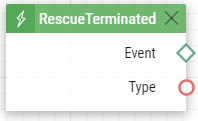
RescueTerminated
The RescueTerminated block defines the event generated by end of rescue mode. Set the rescue modes in Services > Rescue mode in the 2N LiftIP2.0 configuration. If the mode is terminated with ALARM2 without any alarm call received, the action is not executed.
Input parameters
This block has no Input parameters.
Output parameters
- Event – the Event output to invoke the connected Event or Action.
Example
Event generated whenever the rescue mode is terminated using a DTMF password or the ALARM2 button after the alarm call.
 |
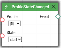
ProfileStateChanged
The ScreenChanged block defines the event generated at the time profile start/stop.
Input parameters
- Profile
- State
- start (default value) – triggers the event at the time profile start.
- stop – triggers the event at the time profile stop.
Output parameters
- Event – the Event output to invoke the connected Event or Action.
Example
 |
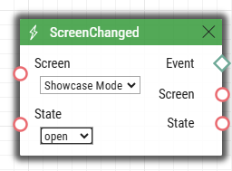
ScreenChanged
The ScreenChanged block defines the event generated whenever the Showcase mode / Idle mode is switched from / to.
Input parameters
- Screen
- Idle Mode – starts when the idle timeout elapses.
- Showcase Mode – starts when any Showcase mode is activated (default value).
- State
- open – triggers the event at the Showcase mode / Idle mode activation (default).
- closed – triggers the event at the Showcase mode / Idle mode deactivation.
Output parameters
- Event – the Event output to invoke the connected Event or Action.
- Screen – writes out the screen identifier.
- State – writes out the screen state.
The event generated at the Showcase mode activation.
 |
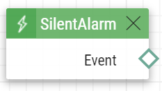
SilentAlarm
The SilentAlarm block defines the event generated upon the silent alarm start. Silent alarm can be started by entering a code higher by 1 than the user switch code. If, thus, a user is assigned switch code 123, silent alarm is started with 124.
Input parameters
This block has no Input parameters.
Output parameters
- Event – the Event output to invoke the connected Event or Action.
Type - type of the event that triggered this block.
Example
The event generated by entering code 112 if a user is assigned code 111.
 |
Time
The Time block defines the event generated every day at a specific time (alarm clock). To limit validity of this event for some days only, use the condition Condition.ProfileState at the started action and specify requested days in the used time profile.
Input parameters
- Time – define time to start the event. Time is entered in hh:mm format.
Output parameters
- Event – the Event output to invoke the connected Event or Action.
Example
Event generated every day at 17:30.
 |
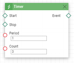
Timer
The Timer block defines the event generated with a defined delay after another specified event with a defined count of repetitions. Define this event to delay the response to the other event by a defined time interval or execute the response several times.
Input parameters
- Start – define the timer starting event (i.e. the row number on the Automation tab on which the event is defined). The parameter is optional. If no value is completed, the timer will be started automatically.
- Stop – define the timer stopping event (i.e. the row number on the Automation tab on which the event is defined). When StopEvent is executed, the timer will stop and will be restarted by StartEvent only. This parameter is optional.
- Period – define the timer period.
- Example of valid values:
10 – 10 seconds (units are unnecessary)
10s – 10 seconds
100ms – 100 milliseconds.
- The minimum period is 100ms.
- Example of valid values:
- Count – define the count of repetitions. The parameter is optional and the default value is 0, which means that the count of timer generated events is unlimited. Value 1 makes the timer behave as a Delay.
Output parameters
- Event – the Event output to invoke the connected Event or Action.
Example
The event generated three times in 1s intervals after the rise of event on row 1:
 |
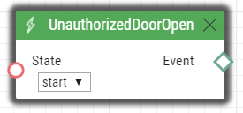
UnauthorizedDoorOpen
The UnauthorizedDoorOpen block defines the event generated whenever an unauthorized door opening is detected.
Input parameters
- State – state of the door sensor that generates the event.
- Start – event start
- End – event end
- Valid values:
Output parameters
- Event – output for generating of the assigned Event or Action.
Example
The event generated by unauthorized door unlocking.
 |
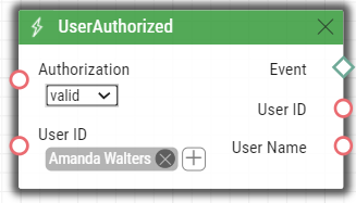
UserAuthorized
The UserAuthorized block defines the event generated at user authorization by any access method (code, PIN, RFID, Bluetooth, fingerprint).
Input parameters
- User ID – define the user/user list. If no value is completed (default value), the user is irrelevant.
Authorization – define the authorization result on which the block reacts
- Valid values:
- valid – valid authorization
- invalid – invalid authorization
- any – valid or invalid authorization
- Valid values:
Output parameters
- Event – Event/Action generating output.
- User ID – user identification that generated this event.
- User Name – user name that generated this event.
Example
The event generated by valid authorization of user Amanda Walters.
 |
Caution
- The User parameter is limited to up to 10 users.
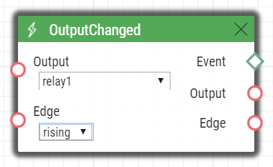
OutputChanged
The OutputChanged defines the event generated at an output change.
Input parameters
- Output – define the logical input.
- Valid values:
- relay1 – relay 1 on basic unit
- relay2 – relay 2 on basic unit
- output1 – output 1 on basic unit
- output2 – output 2 on basic unit
- The list of valid values can be different for each of the 2N IP intercom models, refer to Available Digital Inputs and Outputs.
- Valid values:
- Edge – define the detected output change.
- Valid values:
- falling – falling edge, change from log 1 to log 0
- rising – rising edge, change from log 0 to log 1
- The parameter is optional, the default value is rising.
- Valid values:
Output parameters
- Event – Event/Action generating output.
- Output – detected ID of the input whose change was the last to generate this event. The available values correspond to the Input values.
- Edge – detected change of the output that was the last to generate this event. The available values are falling or rising.
Example
An event generated by the change of the relay 1 output.
 |
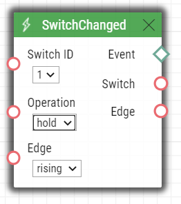
SwitchChanged
The SwitchChanged block generates an event on its output if the configured event occurs.
Input Parameters:
- Switch ID – defines which Switch is used for the event evaluation
- Valid values:
- X – where X is a number of the corresponding Switch (typically 1 .. 4, different models may have different numbers of switches)
- Valid values:
- Operation - defines the type of operation of the Switch that is used for the event evaluation
- Valid values:
- state – Switch can be active or inactive (default value)
- lock – Switch can be locked or unlocked
- hold – Switch can be held or released
- Valid values:
- Edge
- Valid values
- falling – the event occurs if the selected operation changes to logical 0 (i.e. Switch becomes inactive, Switch becomes unlocked, Switch becomes released)
- rising – the event occurs if the selected operation changes to logical 1 (i.e. Switch becomes active, Switch becomes locked, Switch becomes held) (default value)
- Valid values
Output Parameters:
Event – an output event is generated when the input event occurs.
- Switch – the detected ID of the switch whose change was the last to generate this event. The options correspond to the Switch ID parameter values.
- Edge – the detected edge change which was the last to generate this event. The options are falling or rising.
Example
If the block has the following setting: Switch ID = Switch 1, Operation = hold, Edge = rising, the output event will be generated (Event output will trigger event) if Switch 1 becomes held.
 |