4. Actions
Automation – defines the following types of actions:
- ActivateSwitch – switch activation
- ActiveWaveKey – Bluetooth authentication activation
- AnswerCall – incoming call answer
- BeginCall – outgoing call setup
- ControlRtpStream – call RTP stream control
- EndCall – call termination
- FlexiPage – switching display user interface page
- LogAutomationEvent – event logging to the syslog server
- OpenDoor – light and sound signaling of access via a card reader
- PlayUserSound – user sound playing
- SendDtmf – DTMF codes sending
- SendEmail – email sending
- SendHttpRequest – HTTP command sending
- SendMulticastRequest – command sending to multiple devices
- SendWiegandCode – code sending to the Wiegand bus
- SetCameraInput – camera input selection
- SetLed – LED color setting
- SetOnvifVirtualInput – virtual input for ONVIF
- SetOutput – digital output state setting
- SetSecuredState – SecuredState level setting
- StartAutoUpdate – firmware and configuration AutoUpdate
- StartLiftCall – call setup (for 2N LiftIP 2.0 only)
- StartMulticastRecv – audio stream receiving start
- StartMulticastSend – audio stream sending start
- StopMulticastRecv – audio stream receiving stop
- StopMulticastSend – audio stream sending stop
- UploadSnapshotToFtp – snapshot upload to the FTP server
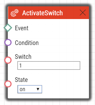
ActivateSwitch
The ActivateSwitch block defines the action necessary for activation of the intercom switch as configured in the Switch 1–4 tags. The activity to be performed depends fully on the particular switch settings (digital output activation, HTTP command sending, etc.). Switch deactivation is controlled by the switch settings too.
Parameters
Event – define the event to launch the action.
Condition – define the condition to be met to execute the action. This parameter is optional.
Switch ID – define the switch to be activated (1 to 4).
- Action – define the state of the bistable switch (parameter does not apply for the monostable switch mode).
- Valid values:
- on – the switch is activated.
- off – the switch is deactivated.
- toggle – the switch is toggled.
- lock – the switch is locked.
- unlock – the switch is unlocked.
- hold – the switch is hold.
- release – the switch is released.
- The parameter is optional, the default value is on.
- Valid values:
Example
Activate switch 1 if the event defined on row 2 arises and the condition defined on row 3 is met:
 |
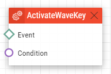
ActivateWaveKey
The ActivateWaveKey block defines the action necessary for the activation of WaveKey authentization process.
Parameters
- Event – define the event to launch the action.
- Condition – define the condition to be met to execute the action. This parameter is optional.
 |
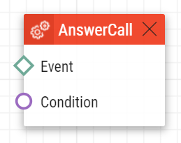
AnswerCall
The AnswerCall block defines the action necessary for answering of an incoming call. In case no call is coming or the incoming call is not ringing, the action will not initiate any activity.
Parameters
- Event – define the event to launch the action.
- Condition – define the condition to be met to execute the action. This parameter is optional.
Example
Answer a call if the event defined on row 2 arises:
 |
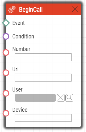
BeginCall
The BeginCall block defines the action necessary for establishing of an outgoing call to the defined telephone number, SIP URI or user number included in the intercom phone book.
Parameters
- Event – define the event to launch the action.
- Condition – define the condition to be met to execute the action. This parameter is optional.
- Number – define the phone number to be called (if 2N IP intercom is registered to the PBX).
- Uri – define the SIP URI to be called: sip:user@domain. Use a special URI in the vms:* format for the Axis Camera Station calls.
- User – define the user to be called.
- Device – define the 2N® IP Mobile application to be called: device_name.
- Enter just one of the above mentioned parameters (Number, Uri, User or Device).
Example
Establish an outgoing call if the event defined on row 2 arises:
 |
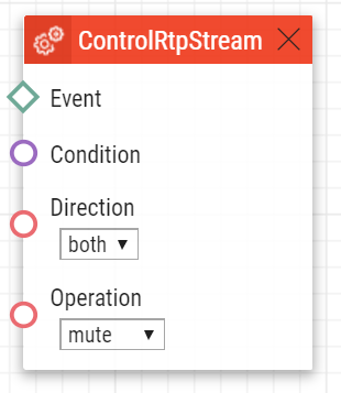
ControlRtpStream
The ControlRtpStream block defines the action that controls the flow of the RTP streams. This action controls only call streams; multicast streams are not affected by this action.
Parameters
- Event – define the event to launch this action.
- Condition – define the condition to be met for the action to be executed. This parameter is optional.
- Direction – define the call RTP stream playing direction.
- Valid values:
- in – incoming stream to the intercom
- out – outgoing stream from the intercom
- both – incoming and outgoing stream.
- The parameter is optional; the default value is both.
- Valid values
- mute – mute the stream.
- unmute – unmute the stream (stream is played).
- Valid values:
Example
Mute call streams in both ways if the event defined on row 2 arises:
 |
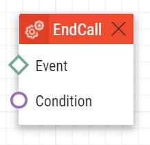
EndCall
The EndCall block defines the action necessary for termination of the currently made call. In case there is no active call via the intercom, the action will not initiate any activity.
Parameters
- Event – define the event to launch the action.
- Condition – define the condition to be met to execute the action. This parameter is optional.
Example
Terminate a call if the event defined on row 2 arises:
 |
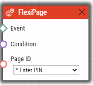
FlexiPage
The FlexiPage block defines an action that switches the custom GUI to the specified page. This feature is only available if Custom GUI is enabled.
Parameters
- Event – define the event that triggers this action.
- Condition – define the condition to be met for the action to be executed. This parameter is optional.
- Page ID – specifies the page the custom GUI switches to.
Example
The custom user interface switches to the Enter PIN page. The page for entering the PIN appears on the device display.
 |
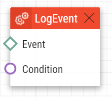
LogAutomationEvent
The LogAutomationEvent block defines the action that logs the event to the syslog server. This block can be used for verification of Automation settings.
Parameters
- Event – define the event that triggers this action.
- Condition – define the condition to be met for the action to be executed. This parameter is optional.
- Log to Event Log – define whether to send this event to Event Log. The default value is 0.
- Name – define the name of this event. This parameter is optional. Its maximum length is 31 characters in Event Log.
- Description – define the description of this event. This parameter is optional. Its maximum length is 63 characters in Event Log.
Example
Send a syslog message with captured event 2 (Event.CardEntered) if the event defined on row 2 arises:
 |
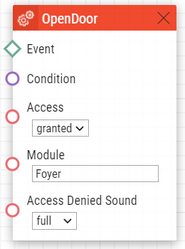
OpenDoor
The OpenDoor block defines an action for light and sound signaling of valid/invalid access via a 2N® IP Verso card reader.
Parameters
- Event – define the event to launch this action.
- Condition – define the condition to be met for the action to be executed. This parameter is optional.
- Access – signal the access validity:
- granted – valid
- denied – invalid
- Module – define the card reader module name.
- Sound – define sound signaling.
- Valid values:
- full – sound signaling for both valid and invalid accesses
- none – no sound signaling
- Valid values:
- Signaling Only – the device does not activate the door switch, it just signals that the door is open.
Example
Signal a valid access at the hall card reader with light and sound.
 |
Note
Other setting examples
- Access granted / Access Denied Sound – none = green light, sound as set for the switch in HW
Access denied / Access Denied Sound – none = red light, no sound
Caution
- The card reader modules connected with the DoorOpen block must be excluded from access control in Hardware / Extending modules. Set Door / Unused for the given model.
- Unnameable modules can be addressed via ext <module_position> , e.g. "ext3".
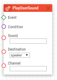
PlayUserSound
The PlayUserSound block defines the user sound playing action.
Parameters
- Event – define the event to launch this action.
- Condition – define the condition to be met for the action to be executed. This parameter is optional.
- Sound – define the sound to be played.
- Valid values for user defined sounds:
- 1–10 – user sound number
- Valid values for predefined sounds (asterisk before the number indicates the use of predefined sound):
- *1 – Modern Ringtone
- *2 – Huge gong
- *3 – Dogs barking
- *4 – Horn/siren
- *5 – Gentle gong
- Valid values for user defined sounds:
- Destination – define the user sound playing destination.
- Valid values:
- speaker – the sound is played on the intercom.
- call – the sound is played into the call.
- multicast – the sound is played via multicast address
- Valid values:
- Channel – define the channel number (0–3) to be controlled.
- The parameter is optional; the default value is speaker.
- The parameter is optional; the default value is speaker.
Example
Play user sound 1 if the event defined on row 2 arises:
 |
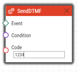
SendDTMF
The Action.SendDTMF block defines action which sends a DTMF code to an active call.
Parameters
- Event – defines the event to launch this action.
- Condition – defines the condition to be met for the action to be executed. This parameter is optional.
- Code – defines sent DTMF characters
- Valid values: 0–9, A–D, F
Example
Send code 1234 into an active call:
 |
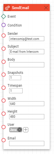
SendEmail
The SendEmail block defines the action that sends an email.
Parameters
- Event – define the event to launch this action.
- Condition – define the condition to be met for the action to be executed. This parameter is optional.
- Sender – define the sender address for outgoing emails.
- Subject – define the subject of the email message to be sent.
- Special placeholders can be entered for the date and time, device Id. These placeholders are replaced with the current values before message sending. Refer to the Body description below.
- Special placeholders can be entered for the date and time, device Id. These placeholders are replaced with the current values before message sending. Refer to the Body description below.
- Body – define the body of the message to be sent. Use the HTML formatting characters. You can enter special placeholders into the text for the date and time, device id to be replaced with the current values before the message is sent. Refer to the placeholder list.
Caution
- The case-depedent placeholders work if Action.SendEmail is generated by any of the supported events. Refer to the placeholder list in Events.
- Snapshots – define the count of snapshots to be enclosed to the email [0, 5].
- The parameter is optional; the default value is 1.
- TimeSpan – define the timespan in seconds for the snapshots enclosed to the email.
- The parameter is optional; the default value is 1.
Tip
You are advised to choose such TimeSpan and Snapshots values that the TimeSpan/Snapshots ratio should be an integer.
Example: Timespan = 8
Snapshots = 5
The latest snapshot will be displayed followed by the earlier ones in a two-second timespan.
If the timespan is lower than the count of available snapshots, some photos are used repeatedly.
- Width – define the resolution width for the camera image to be enclosed. Make sure that the snapshot width complies with one of the supported intercom resolution options.
- The parameter is optional; the default value is 640.
- Height – define the resolution height of the camera image to be enclosed. Make sure that the snapshot height complies with one of the supported intercom resolution options
- The parameter is optional; the default value is 480.
- User – define the user to whom the e-mail will be sent.
- E-mail – define the e-mail address to which the e-mail will be sent. Enter more e-mail addresses if necessary, separated with a comma in inverted commas.
- Valid values:
- user@domain_name
- user@ip_address
- user@domain_name, user@ip_address
- Valid values:
Tip
- The User parameter is preferred to the E-mail parameter.
Example
Send an e-mail to the e-mail address set at user Jana:
 |
Caution
- The User parameter is limited to up to 10 users.
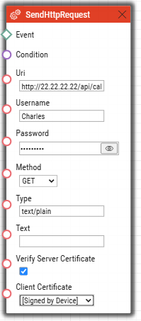
SendHttpRequest
The SendHttpRequest block defines the action necessary for sending of an HTTP command to another LAN device. The HTTP command helps you control other devices in the LAN (IP relay, recording system, another intercom, etc.).
Parameters
- Event – define the event to launch the action.
- Condition – define the condition to be met to execute the action. This parameter is optional.
- Uri – define the standard HTTP URI including the destination address and, optionally, the path and other parameters. The maximum length is 2048 bytes.
- Username – define the username in case authorization is required by the HTTP server. This parameter is optional. The default value is "intercom".
- Password – define the password in case authorization is required by the HTTP server. This parameter is optional.
- Method – define the HTTP request method: GET, POST, PUT, DELETE.
- Type – select the type of the HTTP request body content: "application/json" or "text/plain". Applies to valid methods POST and PUT only.
- Text – select the request text content. Applies to valid methods POST and PUT only.
Verify Server Certificate – verifies the server public certificate against CA certificates uploaded to the device.
Client Certificate – specifies the client certificate and private key used for verifying the intercom's authority to communicate with the server.
Example 1)
Whenever a connected event is generated, HTTP sends a request to the following IP address: 22.22.22.22:
 |
Example 2)
Whenever any key is pressed, its exact identification is sent to the following IP address: 10.27.24.6:
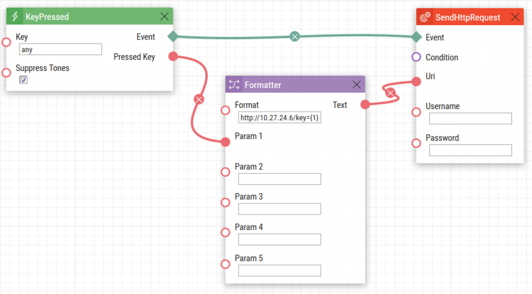 |
Caution
- Both Basic and Digest authentication are supported, we recommend Digest for added security.
Caution
HTTP commands use URL encoding. In the following Automation example:
1. Event.KeyPressed: Key=Any
2. Action.SendHttpRequest: Uri= <Command>; Event=1 will send a message http://192.168.1.1/message=%251 ("%" is encoded as "% 25") after pressing the quick dial button no. 1.
| Button to be pressed | Format in Formatter | Request to be sent |
|---|---|---|
| Quick dial 1 | http://10.27.1.6/message={1} | http://10.27.1.6/message=%251 ("%" is encoded as "%25") |
| Keypad 1 | http://10.27.1.6/message={1} | http://10.27.1.6/message=1 |
| Quick dial 1 | http://10.27.1.6/mess?age={1} | http://10.27.1.6/mess?age=%251 |
| Keypad 1 | http://10.27.1.6/mess?age={1} | http://10.27.1.6/mess?age=1 |
Caution
- Comma-delimited parameter value parsing
One parameter can be comma-delimited into values. The values can be separated with '`' (back apostrophe). Use \ as the escape character for `.
Examples
abc,def → abc and bcd`abc,def`→ abc,bcd
abc\`def → abc`def
abc\def → abcdef
abc\ \def → abc\def (backslash twice in a row)
The validity of notification marked % remains.
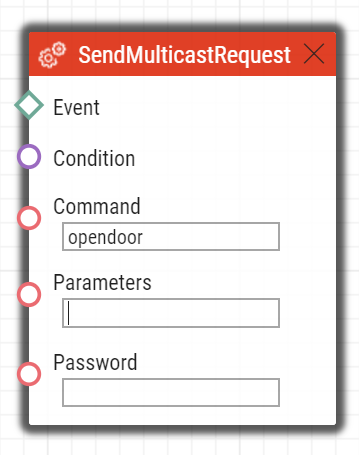
SendMulticastRequest
The SendMulticastRequest block defines the action necessary for user command sending to multiple devices. The sent command can be processed by the MulticastTrigger block. The command is a message sent by UDP to a multicast address (235.255.255.250:4433) and can thus be received by multiple devices at the same time. The message includes the command ID (Command parameter) and additional optional parameters (Params parameters). The message can be password-secured (Password parameter). It is recommended to send these commands with a maximal intensity of 1 command per second.
Parameters
- Event – define the event to execute this action.
- Condition – define the condition to be met for the action to be executed. This parameter is optional.
- Command – define the command identifier to distinguish the command types. The MulticastTrigger block responds to the SendMulticastRequest action only if the command identifier is the same. Any text containing the A–Z, a–z and 0–9 characters can be used for identification.
- Parameters – define one or more (comma-separated) command parameters to be included in the UDP message. Keep the “parameter_name=parameter_value” format.
- Example:
Params=“Address=192.168.1.1”, “Port=10000”
The so-sent parameters will be available in the HttpTrigger event responding to this command as the Address and Port output parameters and can be used in the HttpTrigger-tied actions, for example.
- Password – define the password to secure the command against unauthorised access. The parameter is optional. If no password is completed, the command is not secured. Use any text containing the A–Z, a–z and 0–9 characters.
Example
Send the opendoor command to all the devices with the properly set Event.MulticastTrigger block in the network if the event defined on row 2 arises:
 |
Caution
- Comma-delimited parameter value parsing
One parameter can be comma-delimited into values. The values can be separated with '`' (back apostrophe). Use \ as the escape character for `.
Examples
abc,def → abc and bcd`abc,def`→ abc,bcd
abc\`def → abc`def
abc\def → abcdef
abc\ \def → abc\def (backslash twice in a row)
The validity of notification marked % remains.
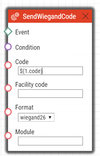
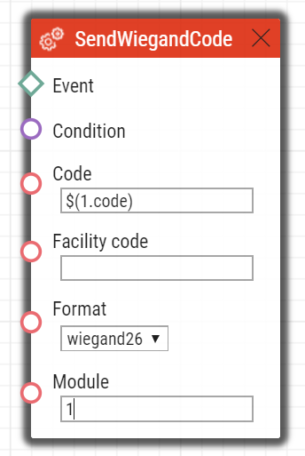
SendWiegandCode
The SendWiegandCode block defines the action for sending of an entered code to another device via the Wiegand interface.
Parameters
- Event – define the event to launch the action.
- Condition – define the condition to be met to execute the action. This parameter is optional.
Code – define the code to be sent via the Wiegand interface. If the entered code exceeds the capacity of the message transferred via the Wiegand interface, the high-order bits are cut. The code can be entered either in decimal or hexadecimal format. You can also enter uuid of a user from the directory. If the uuid exists and the user has Virtual Card configured, the block will send the Virtual Card to the Wiegand interface.
Valid values:
- decimal number
- hexadecimal
- uuid
- Facility code – facility code. The setting applies only to "wiegand26".
- Valid values:
decimal number in a range of 0–255
The parameter is optional; if not set, then unused.
- Valid values:
- Format – define the format of the message sent via Wiegand.
- Valid values:
- wiegand26 – 26 bits
- wiegand32 – 32 bits
- wiegand37 – 37 bits
- The parameter is optional; the default value is wiegand26.
- Valid values:
- Module – define the module via which the code is to be sent.
- Valid values:
- module name configured in the Module name parameter in the Hardware / Extenders / Modules / Wiegand module menu.
- The parameter is mandatory for Verso but not applied for other models.
- Valid values:
Example
Send a code entered by Event.CodeEntered via the Wiegand interface:
 |
For Verso and Access Unit the second line should look like as follows:
 |
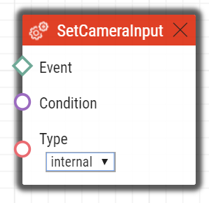
SetCameraInput
The SetCameraInput block defines the action that allows you to switch video signal sources for active calls: the integrated camera, an external IP camera and two analog camera inputs for the 2N® IP Video Kit if necessary. This action cannot be used for video source switching for RTSP streams.
Parameters
- Event – define the event to launch this action.
- Condition – define the condition to be met for the action to be executed. This parameter is optional.
- Type – define the video signal type. A change during a call will apply only for this call. Other video receivers receive video from the same source.
- Valid values:
- internal – internal camera (or external analog video camera connected directly to the device)
- external – external IP camera.
- The parameter is optional, the default value is internal.
- Valid values:
Example
Switch the video signal source to the first external analog camera input if the event defined on row 2 arises:
 |
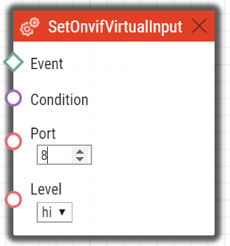
SetOnvifVirtualInput
The SetOnvifVirtualInput block defines the sending action for a change of the virtual input level via the ONVIF protocol. The ONVIF Device Manager (version 2.2.250) can be used for the test.
Parameters
- Event – define the event to launch the action.
- Condition – define the condition to be met to execute the action. This parameter is optional.
- Port – define the virtual port ID.
- Valid values:
- 0–10 – port ID
- Valid values:
- hi – set logical value to true
- lo – set logical value to false.
- The parameter is optional; the default value is hi (true).
- Valid values:
Example
Send information that port 8 has changed its value to 1 via the ONVIF protocol if the event defined on row 2 arises:
 |
The following is sent to ONVIF:
- InputToken: onvif_port_08
- LogicalState:true
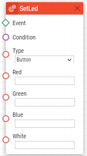
SetLed
The SetLed block defines the action that controls the backlight change of a LED or a set of LEDs on the device. The backlight set in the device web configuration interface is reset after the device restart.
Parameters
- Event – define the event that launches the action.
- Condition – define the condition to be met to execute the action. This parameter is optional.
- Type – define the LED / LED set to be controlled.
- Red – define the red color intensity in the range of 0 to 255. An empty value is considered 0 if another color parameter at least is completed. If all the color parameters are empty, the block deactivates the color setting (i.e. resets the color set in the configuration).
- Green – define the green color intensity in the range of 0 to 255. An empty value is considered 0 if another color parameter at least is completed. If all the color parameters are empty, the block deactivates the color setting (i.e. resets the color set in the configuration).
- Blue – define the blue color intensity in the range of 0 to 255. An empty value is considered 0 if another color parameter at least is completed. If all the color parameters are empty, the block deactivates the color setting (i.e. resets the color set in the configuration).
- White – define the white color intensity in the range of 0 to 255. An empty value is considered 0 if another color parameter at least is completed. If all the color parameters are empty, the block deactivates the color setting (i.e. resets the color set in the configuration).
Example
 |
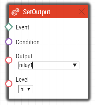
SetOutput
The SetOutput block defines the action necessary for setting of the intercom output to the required level.
Parameters
- Event – define the event that launches the action.
- Condition – define the condition to be met to execute the action. This parameter is optional.
- Output – define the output to be set.
- Valid values:
relay1 – relay 1 on basic unit
relay2 – relay 2 on basic unit
output1 – output 1 on basic unit
output2 – output 2 on basic unit
- There may be different lists of valid values for different 2N IP intercom models; refer to the Available Digital Inputs and Outputs subsection.
- Valid values:
- Level – define the required output level. This parameter is optional.
- Valid values:
lo – output deactivation
hi – output activation (default value).
- Valid values:
Example
Activate Output1 if the event defined on row 2 arises:
 |
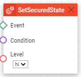
SetSecuredState
The SetSecuredState block defines the action necessary for setting Secured State to the required level. The block only works if the assigned Secured State input is set to None (i.e. no digital input is assigned to the state management).
Parameters
- Event – define the event that launches the action.
- Condition – define the condition to be met to execute the action. This parameter is optional.
- Level – define the required output level.
- Valid values:
- lo – state deactivation
- hi – state activation (defualt value)
- Valid values:
 |
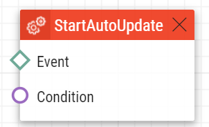
StartAutoUpdate
The StartAutoUpdate block defines the action that runs firmware and configuration auto update. The auto provisioning parameters are configured in the System / Auto Provisioning menu.
Parameters
- Event – define the event to launch this action.
- Condition – define the condition to be met for the action to be executed. This parameter is optional.
Send an email to the email address set to user2@domain_name if event 1 arises:
 |
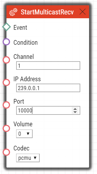
StartMulticastRecv
The StartMulticastRecv block defines the starting action for audio stream receiving and playing. You can control up to four independent transmission channels. The RTP/UDP protocol is used.
Parameters
- Event – define the event to launch this action.
- Condition – define the condition to be met for the action to be executed. This parameter is optional.
- Channel – define the channel number (0–3) to be controlled.
- IP Address – define the audio stream multicast IP address.
- Port – define the UDP port on which audio stream shall be received.
- Volume – define the relative volume level for the audio stream to be played (from -6 dB to +6 dB).
- Valid values:
- -6 – minimum level
- 0 – mean level (default value)
- 6 – maximum level.
- The parameter is optional; the default value is 0.
- Valid values:
- Codec – define the audio codec to be used.
- Valid values:
- pcmu – codec G.711 u-law
- pcma – codec G.711 A-law
- g729 – codec G.729
- g722 – codec G.722
- l16 – codec L16, 16 kHz
- The parameter is optional; the default value is pcmu.
- Valid values:
Example
Start audio stream receiving on multicast IP address 239.0.0.1:10000 via channel 1 if the event defined on row 2 arises:
 |
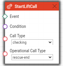
StartLiftCall
The StartLiftCall block defines the action required to initiate an outgoing call of the specified type from 2N LiftIP 2.0. If a call with a higher priority is active, the call initiated by this action joins the queue.
Parameters
- Event – define the event to launch this action.
- Condition – define the condition to be met for the action to be executed. This parameter is optional.
- Call Type – define the lift call type to be initiated. Set the call destinations via the web configuration interface in the Calls section.
- Valid values:
- alarm – alarm call (destination 1)
- alarm2 – alarm call (destination 2)
- operational – operational call
- checking – checking call
- Valid values:
- Operational Call Type – define the operational call type. This parameter is only valid if "operational" is selected in the Call Type.
- Valid values:
rescue-end – an operational call at the end of the rescue mode.
button-error – an operational call whenever the ALARM1 button fails.
button-fixed – an operational call whenever the ALARM1 button is put in operation again after a failure.
audio-error – an operational call whenever the audio test fails (audio error).
audio-fixed – an operational call whenever the audio test is successful after a previous test failure.
- Valid values:
Example
The actions starts a checking call whenever the event defined on row 2 occurs and the condition defined on row 3 is met:
 |
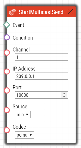
StartMulticastSend
The StartMulticastSend block defines the starting action for audio stream sending to a multicast IP address. You can control up to four independent transmission channels. The RTP/UDP protocol is used.
Parameters
- Event – define the event to launch this action.
- Condition – define the condition to be met for the action to be executed. This parameter is optional.
- Channel – define the channel number (0–3) to be controlled.
- Address – define the audio stream multicast IP address.
- Port – define the UDP port to which audio stream shall be sent.
- Source – define the audio source.
- Valid values:
mic – the audio source is the microphone.
- call – the audio source is the call.
- The parameter is optional; the default value is mic.
- Valid values:
- Codec – define the audio codec to be used.
- Valid values:
- pcmu – codec G.711 u-law
- pcma – codec G.711 A-law
- g729 – codec G.729
- g722 – codec G.722
- l16 – codec L16, 16 kHz
- The parameter is optional; the default value is pcmu.
- Valid values:
Example
Start audio stream sending via channel 1 to address 239.0.0.1:10000 if the event defined on row 2 arises:
 |
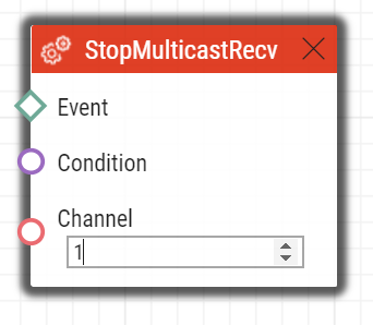
StopMulticastRecv
The StopMulticastRecv block defines the stopping action for audio stream receiving to a multicast IP address.
Parameters
- Event – define the event to launch this action.
- Condition – define the condition to be met for the action to be executed. This parameter is optional.
- Channel – define the channel number (0–3) to be controlled.
Example
Stop audio stream receiving via channel 1 if the event defined on row 2 arises:
 |
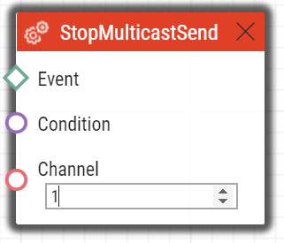
StopMulticastSend
The StopMulticastSend block defines the stopping action for audio stream sending to a multicast IP address.
Parameters
- Event – define the event to launch this action.
- Condition – define the condition to be met for the action to be executed. This parameter is optional.
- Channel – define the channel number (0–3) to be controlled.
Example
Stop audio stream sending via channel 1 if the event defined on row 2 arises:
 |
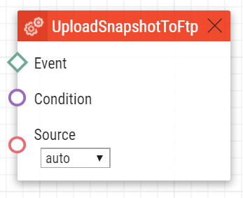
UploadSnapshotToFtp
The UploadSnapshotToFtp block defines the action that sends a camera snapshot to the FTP server. The FTP and snapshot parameters are configured in the Services / Streaming / FTP menu.
Parameters
- Event – define the event to launch this action.
- Condition – define the condition to be met for the action to be executed. This parameter is optional.
- Source – define the video source for the picture to be uploaded to the FTP server.
- Valid values:
- auto – the video source is chosen according to the Hardware / Camera / Common Setting / Default Video Source settings.
- internal – internal camera
- external – external camera.
- The parameter is optional; the default value is auto.
- Valid values:
Example
Upload a picture from the camera to the FTP server if the event defined on row 2 arises:
 |