5. Conditions
Automation defines the following types of conditions:
- True – always true condition
- False – always false condition
- ProfileState – time profile state
- CallState – current call state
- Comparator – value comparison
- AccountState – SIP account registration state
- InputState – digital input state
- FlipFlopRS – RS-type flip-flop
- FlipFlopD – D-type flip-flop
- LogicalAnd – logical AND of conditions
- LogicalOr – logical OR of conditions
- LogicalNot – condition negation
- OnvifVirtualOutputState – VMS virtual port state
- OutputState – output state
- SwitchState – Switch logical level
- SecureState – compares the logical level with the level defined in Level
See below for details on the conditions and their parameters and use.
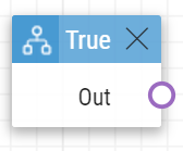
True
The True block defines the condition to be met each time.
Output parameters
- Out
Example
The condition is always met:
 |
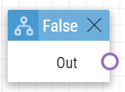
False
The False block defines the condition not to be met any time.
Output parameters
- Out
Example
The condition is always not met.
 |
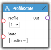
ProfileState
The ProfileState block defines the condition to be met in the case of active/inactive time profile.
Input parameters
- Profile – define the time profile number (1–20 depending on the intercom model).
- State – define the required profile state. This parameter is optional.
- Valid values:
active – active profile (default value)
inactive – inactive profile.
Output parameters
- Out
Example
The condition is met for inactive time profile 1:
 |
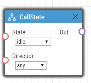
CallState
The CallState block defines the condition to be met in the case of a defined state of the currently made call.
Input parameters
- State – define the call state.
- Valid values:
idle – call is not being made
- connecting – call setup in progress (outgoing calls only)
ringing – ringing in progress
connected – call connected.
- Valid values:
- Direction – define the call direction.
- Valid values:
incoming – incoming calls
outgoing – outgoing calls
any – both directions.
- The parameter is optional, the default value is any.
- Valid values:
Output parameters
- Out
Example
The condition is met for an inactive call:
 |
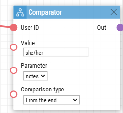
Comparator
The Comparator block defines a condition based on the comparison of the entered value according to the set parameters. The condition is fulfilled (True) if the block finds a match of the (Value) with the (Parameter) according to the selected conditions (Comparison Type).
Input parameters
- User ID – specifies the user whose value to retrieve.
- Value - defines the value to be compared to the parameter. The maximum length is 128 B.
- Parameter – defines the user parameter against which the (Value) is to be compared.
- Valid values:
- notes (default value) (available in ARTPEC devices only, 3.1 Differences between Models)
- name
- lpr – License Plates
- Valid values:
- Comparison Type – defines the comparison method.
- Valid values:
- Exact match (default value) – there is an exact match between the (Value) and the (Parameter) and the value
- Contains – the entire wording of the (Value) is contained in the (Parameter)
- From the beginning – the full wording of the (Value) is at the beginning of the (Parameter)
- From the end - the (Parameter) ends with the (Value)
- Valid values:
Output parameters
- Out
Example
The condition is met if the Note value of the user who performed the previous event ends with the text "she/her".
 |
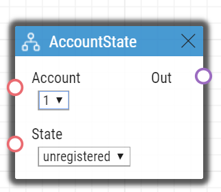
AccountState
The AccountState block defines the condition to be met in the case of a SIP account registered state.
Input parameters
- Account – define the used SIP account
- Valid values:
- 1 – account 1
- 2 – account 2
- 3 – account 3
- 4 – account 4
- The parameter is optional, the default value is 1.
- Valid values:
- State – Define the registration state
- Valid values:
- registered – the account is registered
- unregistered – the account is not registered
- The parameter is optional, the default value is registered.
- Valid values:
Output parameters
- Out
Example
The condition is met for not registered 1 account:
 |
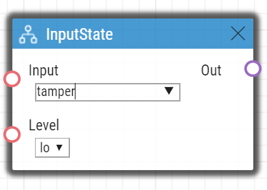
InputState
The InputState block defines the condition to be met in case the defined logic level gets connected to the defined digital input.
Input parameters
- Input – define the digital input.
- Valid values:
tamper – tamper switch
input1 – digital input 1
input2 – digital input 2
cr_input1 – digital input 1 on card reader
cr_input2 – digital input 2 on card reader.
- There may be different lists of valid values for different 2N IP intercom models; refer to the Available Digital Inputs and Outputs subsection.
- Valid values:
- Level – define the required digital input level. The parameter is optional.
- Valid values:
lo – logic 0
hi – logic 1 (default value).
Output parameters
- Out
Example
The condition is met for an activated tamper switch (device not open):
 |
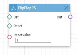
FlipFlopRS
The FlipFlopRS block is a one-bit memory cell (output parameter), whose state changes to 1 or 0 at the rise of defined events. The FlipFlopRS output can be used as a condition for action control in rather complex 2N® Automation applications. It is a simulation of an RS-type flip-flop circuit.
Input parameters
Set – define the event to set the condition into the 'met' state (1).
- Reset – define the event to set the condition into the 'not met' state (0).
- ResetValue – set the condition default value upon restart. The parameter is optional.
- Valid values:
0 – condition is not met (default value)
1 – condition is met.
Output parameters
- Out
Example
The condition is met at the rise of event 1 and not met at the rise of event 2:
 |
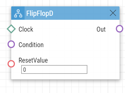
FlipFlopD
The FlipFlopD block is a one-bit memory cell (output parameter), which records the state of another condition at the moment of rise of the defined event for later use. The FlipFlopD output can be used as a condition for action control in rather complex 2N® Automation applications. It is a simulation of a D-type flip-flop circuit.
Input parameters
Clock – define the event during which the current state of the condition is to be recorded.
- Condition – define the condition to be recorded at the rise of the ClockEvent.
- ResetValue – set the condition default value upon restart. The parameter is optional.
- Valid values:
0 – condition is not met (default value)
1 – condition is met.
Output parameters
- Out
Example
The state of the condition is same as the state of condition 2 at the rise of event 1:
 |
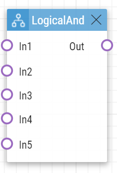
LogicalAnd
The LogicalAnd block helps you create groups of conditions. The block is fulfilled if all the conditions in the defined group are met.
Input parameters
- In1 – define the condition to be met.
- In2 – define the condition to be met.
- In3 – define the condition to be met.
- In4 – define the condition to be met.
- In5 – define the condition to be met.
Output Parameters
- Out
Example
The condition is met if conditions 1, 2 and 3 are met at the same time:
 |
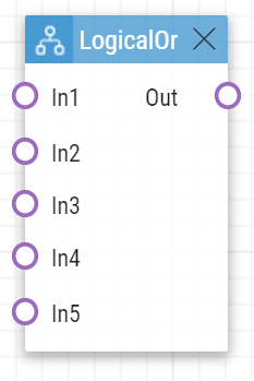
LogicalOr
The LogicalOr block helps you create groups of conditions. The block is fulfilled if one condition at least of the defined group is met.
Input parameters
- In1 – define the condition to be met.
- In2 – define the condition to be met.
- In3 – define the condition to be met.
- In4 – define the condition to be met.
- In5 – define the condition to be met.
Output parameters
- Out
Example
The condition is met if conditions 1, 2 or 3 are met:
 |
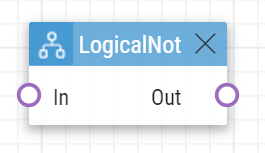
LogicalNot
The LogicalNot block defines the condition to be met in case another defined condition is not met.
Input parameters
- In
Output parameters
- Out
Example
The condition is met in case condition 1 is not met:
 |
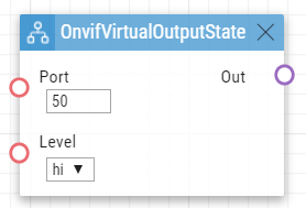
OnvifVirtualOutputState
The OnvifVirtualOutputState block defines the condition to be met when the set virtual port state is active.
Input parameters
- Port – define the port to be observed. The valid values are 50–54.
- Level – define the logical value of the port to be observed. The valid values are high and low.
Output parameters
- Out
 |
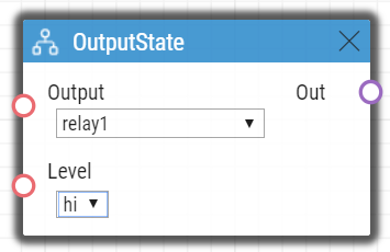
OutputState
OutputState defines the condition that matches the logical state of the output.
Input parameters
- Output – define the digital input.
- Valid values:
- relay1 – relay 1 on basic unit
- relay2 – relay 2 on basic unit
- output1 – output 1 on basic unit
- output2 – output 2 on basic unit
- There may be different valid values for different 2N IP intercom models; refer to Subs. Available Digital Inputs and Outputs.
- Valid values:
- Level – define the required digital input level. The parameter is optional.
- Valid values:
- lo – logical 0
- hi – logical 1 (default value)
- Valid values:
Output parameters
- Out
Example
The condition is met if relay 1 is active.
 |
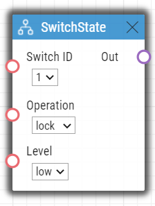
SwitchState
The SwitchState block produces logical 0 or logical 1 based on a condition defined by parameters Switch ID, Operation and Level.
Input parameters:
- Switch ID – defines which Switch is used for the condition evaluation
- Valid values:
- X – where X is a number of the corresponding Switch (typically 1 .. 4, different models may have different numbers of switches)
- Valid values:
- Operation – defines the type of operation of the Switch which is used for the condition evaluation
- Valid values:
- state – Switch can be active or inactive (default value)
- lock – Switch can be locked or unlocked
- hold – Switch can be held or released
- Level
- Valid values
- lo – the condition is met if the selected operation is in logical 0 (i.e. Switch is inactive, Switch is unlocked, Switch is released)
- hi – the condition is met if the selected operation is in logical 1 (i.e. Switch is active, Switch is locked, Switch is held) (default value)
- Valid values
Output parameters:
- Out – the value reflects if the condition is met.
Example
If the block has setting Switch ID = Switch 1, Operation = lock, Level = low, the condition will be met (Out will be in logical 1) if Switch 1 is unlocked.
 |
SecureState
The SecureState block compares the secured state logical level with the value defined in the Level parameter.
Parameters
- Level – define the condition.
- Valid values:
- lo – logic 0
- hi – logic 1 (default value)
- Valid values:
- Out – the values indicates whether or not the condition is met.
 |