5.3.3 SIP 1 / SIP 2
The 2N IP intercoms allow two independent SIP accounts to be configured. Thus, the intercom can be registered under two phone numbers, with two different SIP exchanges and so on. Both the SIP accounts process incoming calls equivalently. Outgoing calls are primarily processed by account SIP 1, or, if account SIP 1 is not registered (due to SIP exchange error, e.g.), by account SIP 2. Select the account number for the phone numbers included in the phone directory to specify the account to be used for outgoing calls (example: 2568/1 - calls to number 2568 go via account SIP 1, sip:1234@192.168.1.1 calls to sip uri via account SIP 2).

- SIP Account Enable – allow the SIP account use for calling. If disallowed, the account cannot be used for making outgoing calls and receiving incoming calls.
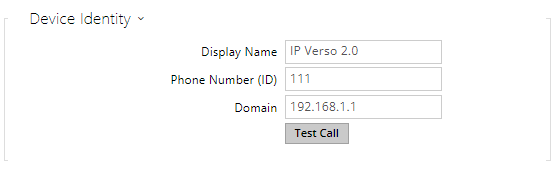 |
- Display Name – set the name to be displayed as CLIP on the called party's phone.
- Phone Number (ID) – set the intercom phone number (or another unique ID including characters and digits). Together with the domain, this number represents a unique intercom identification in calls and registration.
- Domain – set the domain name of the service with which the intercom is registered. Typically, it is identical with the SIP Proxy or Registrar address.
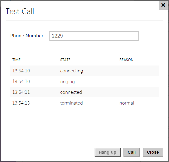
- Test Call – display a dialogue window enabling you to make a test call to a selected phone number, see below.
 |
 |
- Authentication ID – enter the alternative user ID for the device authentication. Phone Number (ID) will be used if this parameter is left empty.
- Password – enter the password for authentication. The parameter is applied on if your PBX requires authentication.
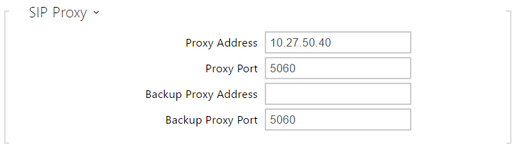 |
- Proxy Address – set the SIP Proxy IP address or domain name.
- Proxy Port* – set the SIP Proxy port. The device uses the default port according to the transport layer (5060 or 5061) or a port obtained from DNS in case the parameter is empty or set to 0.
- Backup Proxy Address – set the SIP Proxy IP address or domain name to be used where the main proxy fails to respond to requests.
- Backup Proxy Port* – set the backup SIP Proxy port. The device uses the default port according to the transport layer (5060 or 5061) or a port obtained from DNS in case the parameter is empty or set to 0.
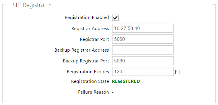 |
- Registration Enabled – enable intercom registration with the set SIP Registrar.
- Registrar Address – set the SIP Registrar IP address or domain name.
- Registrar Port* – set the SIP Registrar port. The device uses the default port according to the transport layer (5060 or 5061) or a port obtained from DNS in case the parameter is empty or set to 0.
- Backup Registrar Address – set the SIP registrar IP address or domain name to be used where the main registrar fails to respond to requests.
- Backup Registrar Port* – set the backup SIP registrar port. The device uses the default port according to the transport layer (5060 or 5061) or a port obtained from DNS in case the parameter is empty or set to 0.
- Registration Expires – define the registration expiry, which affects the network and SIP Registrar load by periodically sent registration requirements. The SIP Registrar can modify the expiry limit without letting you know.
- Registration State – display the current registration state (unregistered, registering..., registered, unregistering...).
- Failure Reason – display the reason for the last registration attempt failure: the last error reply of the registrar, e.g. 404 Not Found.
Tip
- To set the Outbound Proxy complete the Outbound Proxy address into the Proxy address and Registrar address parameters. Domain = Registrar address.
Caution
- If the parameter* is empty or set to 0, the default port is used according to the selected transport protocol (5060 for TCP or UDP, 5061 for TLS).
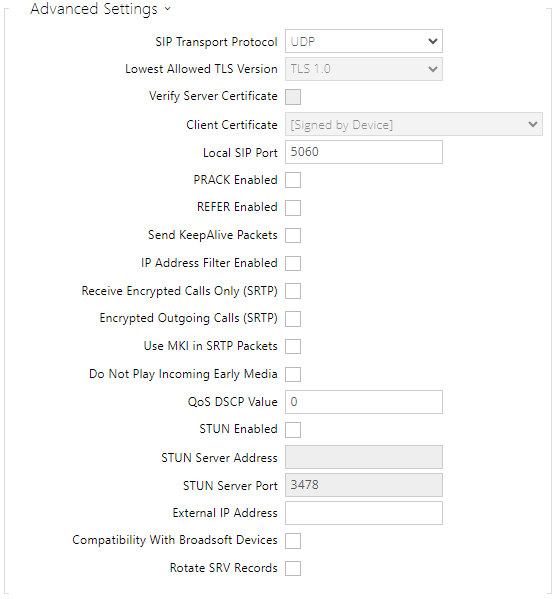 |
- SIP Transport Protocol – set the SIP communication protocol: UDP (default), TCP or TLS.
- Lowest Allowed TLS Version – define the lowest TLS version to be connected to the devices.
- Verify Server Certificate – verify the SIP server public certificate against the CA certificates uploaded in the device.
- Client Certificate – specify the client certificate and private key used for verifying the intercom’s authority to communicate with the SIP server.
- Local SIP Port – set the local port to be used for SIP signalling. The parameter is not applied until the intercom is restarted. The default value is 5060.
- PRACK Enabled – enable the PRACK method for reliable confirmation of SIP messages with codes 101–199.
- REFER Enabled – enable call forwarding via the REFER method.
- Send KeepAlive Packets – set whether the device should periodically send STUN/CRLF packets to the registrar as well as SIP OPTIONS during calls to keep an already established connection active.
- IP Address Filter Enabled – enable the blocking of SIP packet receiving from addresses other than SIP Proxy and SIP Registrar. The primary purpose of the function is to enhance communication security and eliminate unauthorised phone calls.
- Receive Encrypted Calls Only (SRTP) – set that SRTP encrypted calls shall only be received on this account. Unencrypted calls will be rejected. At the same time, TLS is recommended as the SIP transport protocol for higher security.
- Encrypted Outgoing Calls (SRTP) – set that outgoing calls shall be SRTP encrypted on this account. At the same time, TLS is recommended as the SIP transport protocol for higher security.
- Use MKI in SRTP Packets – enable the use of MKI (Master Key Identifier) if required by the counterparty for master key identification when multiple keys rotate in the SRTP packets.
- Adaptive Control of Video Quality – enable the use of extended RTP profile for feedback via the RTCP (RTP/AVPF). Enable the use of interactive video quality control according to RFC-4585 allowing for adaption of the video data flow to the currently available network connection quality.
- Do Not Play Incoming Early Media – disable playing of the incoming audio stream before call pick-up (early media), which is sent by some PBXs or other devices. A standard local ringtone is played instead.
- QoS DSCP Value – set the SIP packet priority in the network. The set value is sent in the TOS (Type of Service) field in the IP packet header. Value is entered in decimal format.
Tip
| Recommended QoS DSCP Values | |||
|---|---|---|---|
| QoS decimal | QoS hexadecimal | Qos DSCP decimal (ToS) | |
| Signaling | 24 / 26 | 18 / 1A | 96 / 104 |
| Audio | 46 | 2E | 184 |
| Video | 40 | 28 | 160 |
- STUN Enable – enable STUN functionality for the SIP account. Address and ports acquired from the configured STUN server will be used in SIP headers and SDP media negotiation.
- STUN Server Address – set the IP address of the STUN server that will be used for this SIP account.
- STUN Server Port – set the port of the STUN server that will be used for this SIP account.
- External IP Address – set the public IP address or name of the router to which your intercom is connected. If the intercom IP address is public, leave this field blank.
- Compatibility with Broadsoft Devices – set the Broadsoft PBX compatibility mode. Having received re-invite from a PBX in this mode, the intercom replies by repeating the last sent SDP with currently used codecs instead of sending a complete offer.
- Rotate SRV Records – allow SRV record rotation for SIP Proxy and Registrar. This is an alternative method of transition to backup servers in the event of main server failure or unavailability.
Caution
- To use the NAPTR / SRV DNS query, cancel the Proxy/Registrar port setting.
Video
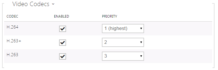 |
- Enable/disable the use of video codecs for call setups and set their priorities.
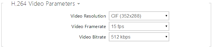 |
- Video Resolution – set the video resolution for phone calls.
- Video Framerate – set the video frame rate for phone calls.
- Video Bitrate – set the video stream bit rate for phone calls.
 |
PTZ Mode – enable the PTZ (Pan-Tilt-Zoom) function to control the camera display area during the call via DTMF (GOLD license required) from your IP phone numeric keypad.
If the PTZ mode is enabled, you can control the camera via your IP phone numerical keypad. Press the * key to enable/disable PTZ. The meanings of the IP phone keys in the PTZ mode are as follows:
IP phone key
PTZ mode function
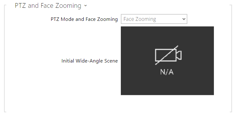
* Enable/disable PTZ 1 Zoom in 3 Zoom out 2 Move zoom region up 4 Move zoom region to the left 6 Move zoom region to the right 8 Move zoom region down 5 Return to initial state PTZ and Face Zooming – enable the PTZ (Pan-Tilt-Zoom) and Face Zooming functions, which allow you to select a cropped camera image display during a call. If Face Zooming is selected, the camera zooms in on the face of the user standing at the device. If Face Zooming – Tilt Only is selected, the cropped image just moves to capture the face.
Caution
- The Face Zooming function is only available with the AXIS ARTPEC-7 equipped models.
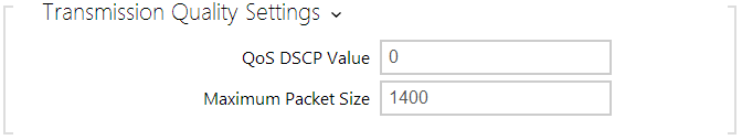 |
- QoS DSCP Value – set the video RTP packet priority in the network. The set value is sent in the TOS (Type of Service) field in the IP packet header. The recommended QoS values valid for signaling, audio and video are shown in the table above.
- Maximum Packet Size – set the size limit for the video RTP packets to be sent.
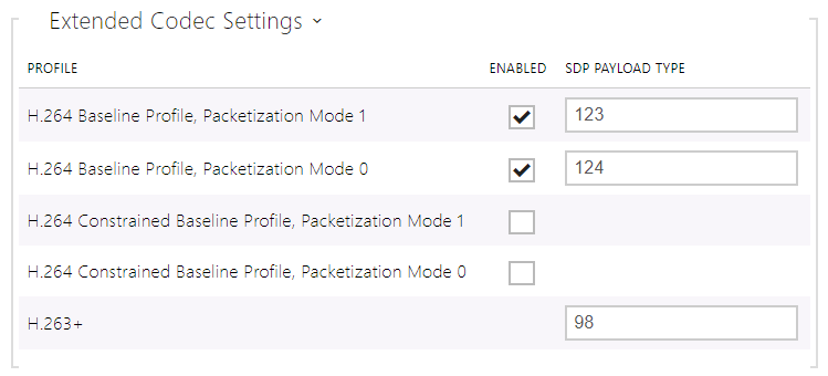 |
- H.264 Baseline Profile, Packetization Mode 1
- H.264 Baseline Profile, Packetization Mode 0
- H.264 Main Profile, Packetization Mode 1
- H.264 Main Profile, Packetization Mode 0
- H.264 High Profile, Packetization Mode 1
- H.264 High Profile, Packetization Mode 0
- H.264 Constrained Baseline Profile, Packetization Mode 1
- H.264 Constrained Baseline Profile, Packetization Mode 0
- Enabled – enable the packetization mode and set the payload type for each codec. The payload type can be selected automatically in case it cannot be set manually.
- SDP Payload Type – set the payload type for video codec H.264 (packetization mode 1). Set a value from the range of 96 through 127, or 0 to disable this codec option.
- H.263+
- SDP Payload Type – set the payload type for video codec H.263+. Set a value from the range of 96 through 127.
 |
- Use sendrecv Attribute for Video – the setting was earlier named Compatibility with Polycom phones. This setting provides compatibility with some third party devices (Polycom/Cisco and others). In this mode, the intercom sends sendrecv instead of sendonly in the SDP message in the codec offer for video.
Tip
- For the Video Preview feature at the Grandstream GXV 3275 phone (video transferred via Early Media) no configuration is needed. Check your PBX vendor whether this feature is supported by your PBX system.
- For the Video Preview feature at the Gigaset Maxwell 10 phone (video transferred via jpg images) it is necessary to set Connection Type to Unsecure and Authentication to None at the Camera API in HTTP API.
Audio
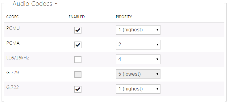 |
- Enable/disable the use of audio codecs for call setups and set their priorities. Broadband codecs L16 and G.722 are available in selected intercom models only. Codec G.729 is available for all the 2N IP intercoms.
The tab below helps you define how DTMF characters shall be sent from the intercom. Check the DTMF sending options and settings of the opponent to make the function work properly.
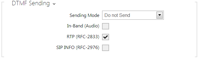 |
- Sending Mode – define whether it is possible to send DTMF during a call by pressing 0 through 9, * and # on the intercom numeric keypad. Set the sending mode for incoming/outgoing/all calls.
- In-Band (Audio) – enable classic DTMF dual tone sending in the audio band.
- RTP (RFC-2833) – enable DTMF sending via the RTP according to RFC-2833.
- SIP INFO (RFC-2976) – enable DTMF sending via SIP INFO messages according to RFC-2976.
The tab below helps you define how DTMF characters shall be received from the intercom. Check the DTMF receiving options and settings of the opponent to make the function work properly.
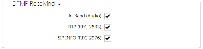 |
- In-Band (Audio) – enable classic DTMF dual tone receiving in the audio band.
- RTP (RFC-2833) – enable DTMF receiving via the RTP according to RFC-2833.
- SIP INFO (RFC-2976) – enable DTMF receiving via SIP INFO messages according to RFC-2976.
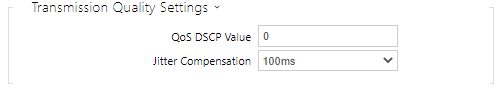 |
- QoS DSCP Value – set the audio RTP packet priority in the network. The set value is sent in the TOS (Type of Service) field in the IP packet header. Value is entered in decimal format. The recommended QoS values valid for signaling, audio and video are shown in the table above.
- Jitter Compensation – set the buffer capacity for jitter compensation in audio packet transmissions. A higher capacity improves the transmission resistance at the cost of a greater sound delay.