5.3.4 Local Calls
This tab contains settings for connection of the 2N answering units to the intercom. The main parameter is the access key, which secures the connection and enables you to create multiple independent groups of intercoms and 2N answering units within the local network. It also contains the video transmission settings.
 |
- Enable Local Calls – enable calls between 2N devices in the LAN. With this function off, the other LAN devices cannot locate this device, i.e. cannot call the device in the device:device_ID format.
 |
- Device ID – set the device ID to be displayed in the LAN device list in all the 2N devices in one and the same LAN. You can direct a call to this device by setting the user phone number as device:device_ID in these devices.
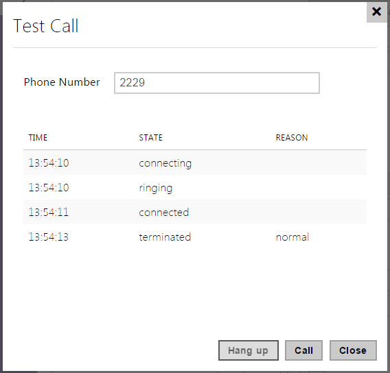
Test call – display a dialogue window enabling you to make a test call to a selected phone number, see below.
 |
- Access Key 1–3 – set the access key to be shared by the intercom and 2N answering unit. If the access keys do not match in the intercom and2N answering unit, the intercom cannot call the 2N answering unit and the 2N answering unit cannot receive video from the intercom. Each intercom can be assigned up to three access keys and thus become a member of up to three independent 2N answering unit groups. The Access key length is up to 63 characters.
- The access key cannot be used with 2N Indoor Touch firmware v. 2 or 3 where it has to be set as empty. The access key can only be used for 2N Indoor Touch version 4 or higher.
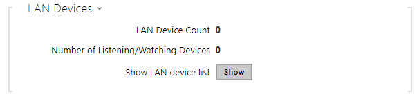 |
- LAN Device Count– display the current count of local 2N answering units connected to the intercom, i.e. those registered with the intercom.
- Number of Listening/Watching Devices – display the current count of 2N answering units watching video streams from the intercom.
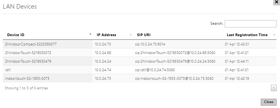
- Show LAN device list – display the list of local 2N answering units.
 |
Video
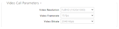 |
- Video Resolution – set the video resolution for phone calls (for video codec).
- Video Framerate – set the video frame rate for phone calls (for video codec).
- Video Bitrate – set the video stream bit rate for phone calls (for video codec).
 |
- Enable Video Preview – enable video preview multicast transmission.
- Multicast Group – set the multicast address to which the intercom video stream shall be sent. Select one of the 8 preset addresses or set the mode in which the intercom selects the address automatically.
- Low Bandwidth Mode – reduces the quality of the video preview stream to conserve bandwidth.
 |
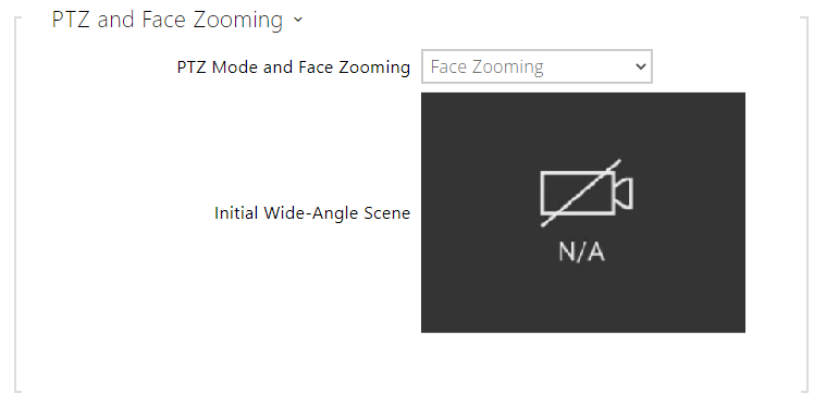
PTZ Mode – enable the PTZ (Pan-Tilt-Zoom) function to control the camera display area during the call via DTMF (GOLD license required) from your IP phone numeric keypad.
If the PTZ mode is enabled, you can control the camera via your IP phone numerical keypad. Press the * key to enable/disable PTZ. The meanings of the IP phone keys in the PTZ mode are as follows:
IP phone key
PTZ mode function
* Enable/disable PTZ 1 Zoom in 3 Zoom out 2 Move zoom region up 4 Move zoom region to the left 6 Move zoom region to the right 8 Move zoom region down 5 Return to initial state PTZ and Face Zooming – enable the PTZ (Pan-Tilt-Zoom) and Face Zooming functions, which allow you to select a cropped camera image display during a call. If Face Zooming is selected, the camera zooms in on the face of the user standing at the device. If Face Zooming – Tilt Only is selected, the cropped image just moves to capture the face.
Caution
- The Face Zooming function is only available with the AXIS ARTPEC-7 equipped models.
Audio
The tab below helps you define how DTMF characters shall be sent from the intercom. Check the DTMF sending options and settings of the opponent to make the function work properly.
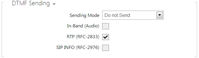 |
- Sending Mode – define whether it is possible to send DTMF during a call by pressing 0 through 9, * and # on the intercom numeric keypad. Set the sending mode for incoming/outgoing/all calls.
- In-Band (Audio) – enable classic DTMF dual tone sending in the audio band.
- RTP (RFC-2833) – enable DTMF sending via the RTP according to RFC-2833.
- SIP INFO (RFC-2976) – enable DTMF sending via SIP INFO messages according to RFC-2976.
The tab below helps you define how DTMF characters shall be received from the intercom. Check the DTMF receiving options and settings of the opponent to make the function work properly.
 |
- In-Band (Audio) – enable classic DTMF dual tone receiving in the audio band.
- RTP (RFC-2833) – enable DTMF receiving via the RTP according to RFC-2833.
- SIP INFO (RFC-2976) – enable DTMF receiving via SIP INFO messages according to RFC-2976.
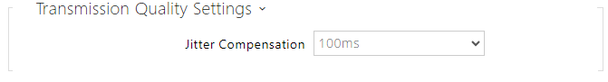 |
- Jitter Compensation – set the buffer capacity for jitter compensation in audio packet transmissions. A higher capacity improves the transmission resistance at the cost of a greater sound delay.