5.5.9 Extenders
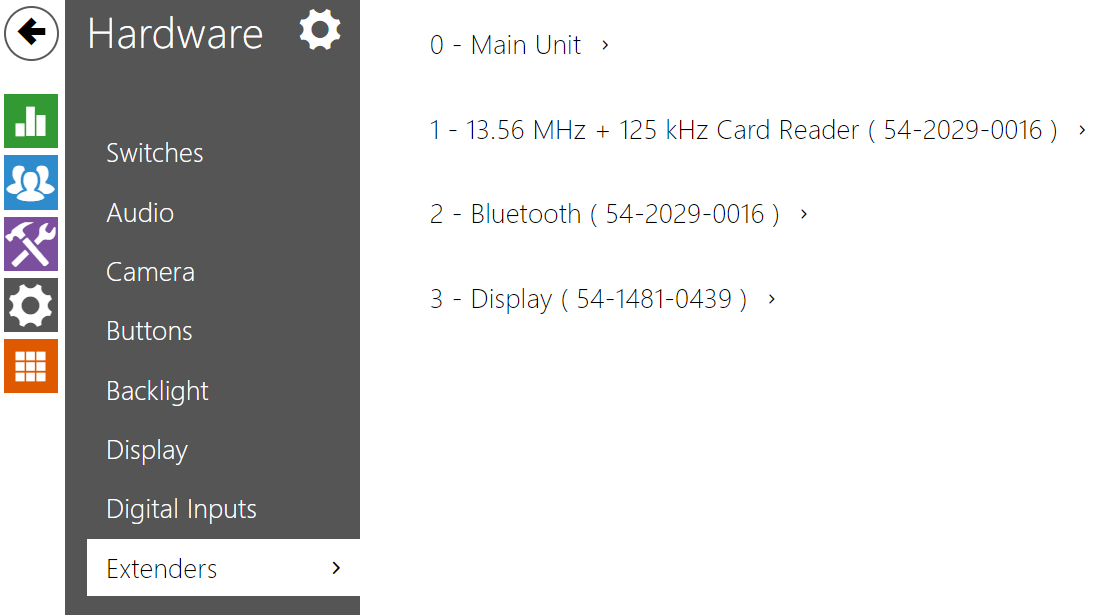 |
The 2N IP Verso / 2.0, 2N IP Style and 2N IP Force 2.0 intercoms can be extended by means of extending modules connected to the intercom basic unit via a VBUS. The following modules are available:
- Five-button module
- Keypad module
- Infopanel module
- Card reader module
- Bluetooth module
- I/O module
- Wiegand module
- OSDP module
- Induction loop module
- Display module
- Fingerprint reader
- Touch keypad
- Touch keypad & RFID reader 125 kHz, 13.56 MHz
- Bluetooth & RFID reader 125 kHz, 13.56 MHz
- Touch keypad & Bluetooth & 125 kHz, 13.56 MHz RFID reader
The modules are chain-like interconnected. Each of the modules has its number depending on the chain position (the first module has number 1). The basic unit is a special type of module and has number 0.
You can configure each module separately. The parameters are specific for the given module type.
Caution
- The connected module is not detected automatically. Restart the device to see the module in the extender list.
In case the firmware versions of the module to be connected and the main unit are incompatible, the module will not be detected. Therefore, it is necessary to update the device firmware after the modules are connected. Use the device web interface in the System > Maintenance > System configuration section for firmware upgrade.
Caution
- Be sure to configure the replaced modules. The configuration is tied with the module serial number.
Note
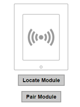
- The extending modules are displayed in the order corresponding to their interconnection. The modules connected further from the basic unit are listed below. If more modules of the same type are connected to one intercom, it may be difficult to assign a setting to a particular module. In this case, identify the modules connected using the Locate Module button. The module will flash shortly several times when you press the button.
Caution
- Having connected the card reader module via the VBUS cable to a device into which the 2N PICard reading keys have been uploaded, remember to pair the module with the device. Without pairing, the card reader module will not have access to the reading keys and be unable to read encrypted cards. Click Pair Module to pair the module.
 |
Caution
- Module Name has to be unique.
- Unnameable modules can be addressed via ext <module_position>.
Tip
- Place the mouse cursor onto the module image to display the module's basic production and software information.
Main Unit Module Configuration
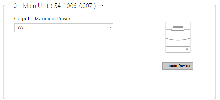 |
- Locate Device – optical and acoustic signaling of a device. Note: Optical signaling is possible only if the device is equipped with control backlight (Verso, Base, Vario, Force, Safety and Uni). If a speaker is not integrated in the device, make sure than an external speaker is connected (Audio Kit and Video Kit) to use sound signaling.
Button Module Configuration
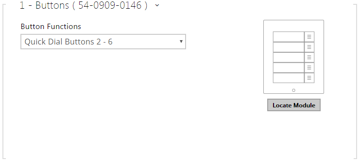 |
- Button Function – assign user positions to the buttons.
Keypad Module Configuration
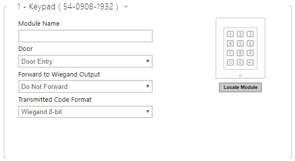 |
- Module Name – set the module name for logging events from the keypad.
- Door – set the reader direction (Door Entry, Door Exit) for the Attendance system purposes.
- Forward to Wiegand Output – set a group of Wiegand outputs to which all pressed keys are to be forwarded.
- Transmitted Code Format – select a 4bit or 8bit (higher security) format for the codes to be transmitted.
Infopanel Module Configuration
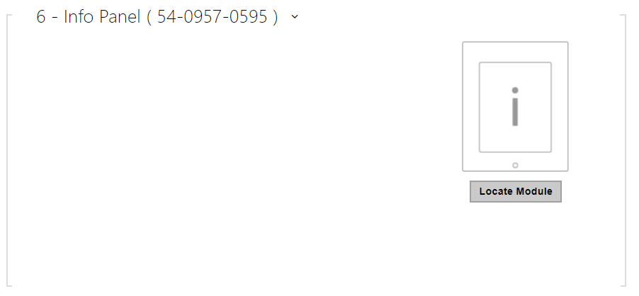 |
- No parameters are available to the public at present.
125 kHz Card Reader Module Configuration
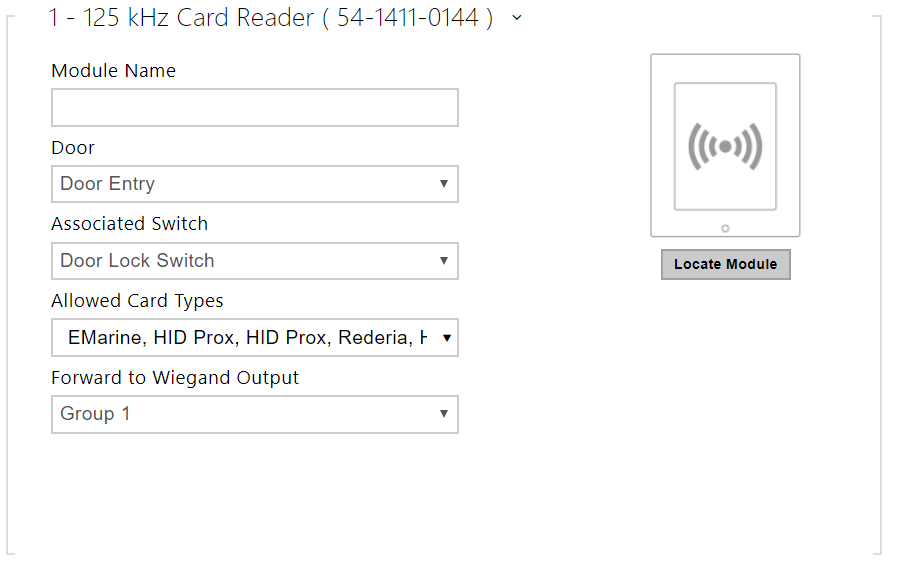 |
- Module Name – set the module name for card reader logging purposes.
- Door – set the reader direction (Door Entry, Door Exit) for the Attendance system purposes.
- Associated Switch – set the switch to be activated after user authentication via this module. If you set Door Lock Switch, the authentication rules specified in Hardware / Door will be used.
- Allowed Card Types – set the type of a card to be accepted by the card reader. If possible, choose one card type and disable the others. Some card type combinations are not supported as they may negatively affect the data reading quality.
- Forward to Wiegand Output – set a group of Wiegand outputs to which all the received RFID card IDs will be resent.
Tip
- To accelerate card reading, you are recommended to select the card types used by the user in the module settings.
13.56 MHz Card Reader Module Configuration
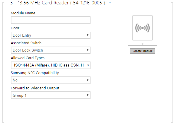 |
- Module Name – set the module name for card reader logging purposes.
- Door – set the reader direction (Door Entry, Door Exit) for the Attendance system purposes.
- Associated Switch – set the switch to be activated after user authentication via this module. If you set Door Lock Switch, the authentication rules specified in Hardware / Door will be used.
- Allowed Card Types – set the type of a card to be accepted by the card reader. If possible, choose one card type and disable the others. Some card type combinations are not supported as they may negatively affect the data reading quality.
- Samsung NFC Compatibility – enable NFC compatibility with the Samsung phones.
- Forward to Wiegand Output – set a group of Wiegand outputs to which all the received RFID card IDs will be resent.
Tip
- To accelerate card reading, you are recommended to select the card types used by the user in the module settings.
Bluetooth Module Configuration
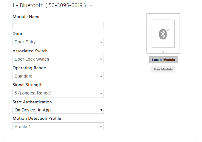 |
- Module Name – set the module name for logging events from the Bluetooth module.
- Door – set the reader direction (Not specified, Arrival, Departure) for the Attendance system purposes.
- Associated Switch – set the switch to be activated after user authentication via this module. If you set Door Lock Switch, the authentication rules specified in Hardware / Door will be used.
- Operating Range – Limited Operating Range mode reduces the operating distance to up to 5 m for Bluetooth signal.
- Signal Strength – set the signal range (5 = maximum, 1 = minimum), i.e. the distance over which the Bluetooth module can communicate with a mobile phone. It is recommended that the actual signal range is tested while setting, as it is affected by a number of factors (installation layout, mobile phone type and position in particular).
- Start Authentication – set the authentication method for a mobile phone:
- In App – authentication has to be confirmed by tapping on an icon in the application running in a mobile phone.
- On Device – touch the card reader having a phone with paired My2N to confirm authentication.
- Via Motion Detection – authentication will be launched by motion detection via a phone with the paired My2N application.
- Motion Detection Profile – set the motion detection profile for the module authentication via a mobile phone.
I/O Module Configuration
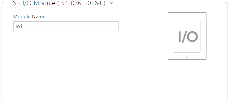 |
- Module Name – set the module name for input/output specification in the SetOutput, GetInput and InputChanged objects in Automation.
Wiegand Module Configuration
The Wiegand module is equipped with the input and output Wiegand interfaces, which are mutually independent, have separate settings and can receive and send codes at the same time. The Wiegand input helps you connect such equipment as RFID card readers, biometric readers and so on. With the Wiegand output, you can connect the intercom to the security system in your building, for example (to send IDs of the RFID cards tapped on the RFID reader or codes received on any Wiegand input). The 2N Wiegand Isolator is also equipped with one logical input and one logical output, which can be controlled via Automation.
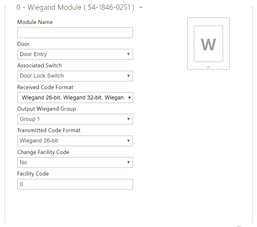 |
- Module Name – set the module name for input/output specification in the SetOutput, GetInput and InputChanged objects in the 2N Automation.
- Door – set the reader direction (Arrival, Departure) for the Attendance system purposes.
- Associated Switch – set the switch to be activated after user authentication via this module. If you set Door Lock Switch, the authentication rules specified in Hardware / Door will be used.
- Received Code Format – set the format for the codes to be received (Wiegand 26, 32, 37 and RAW).
- Output Wiegand Group – assign the output Wiegand to a group to which the codes from the connected card readers or Wiegand inputs can be resent.
- Transmitted Code Format – set the format for the codes to be transmitted (26-bit, 32-bit, 37-bit and RAW format, 35-bit, Corp. 1000, 48-bit, Corp. 1000 and Auto).
- Change Facility Code – set the first code part via Wiegand. This applies to Wiegand OUT for 26-bit code format. Contact your security system supplier to know if the Facility Code is requested.
- Facility Code – define the 2N IP device location in the security system. Enter a decimal value for the location (0–255).
OSDP Module Configuration
The OSDP module is equipped with an (input-output) OSDP (RS-485) interface. OSDP helps you connect the 2N IP intercom to, e.g., a building security system or Control Panel (to send the RFID card IDs read on the connected RFID reader or PIN codes).
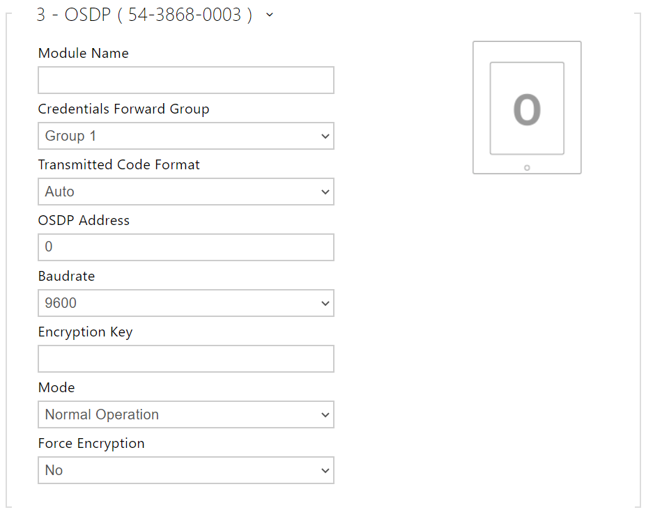 |
- Module Name – set the module name. The module name is used for input / output specification in Automation.
- Credentials Forward Group – assign the OSDP output to the group to which codes from the connected card readers or OSDP inputs can be resent.
- Transmitted Code Format – set the code format to be transmitted.
- OSDP Address – OSDP module address ranging from 0 to 126 on an OSDP line.
- Baudrate – set the communication rate in compliance with the device connected.
- Encryption Key – set your own key for encrypted communication.
- Mode – use the installation mode for encryption key remote setting on the peripheral if enabled. Once the encryption key is received, the normal operation is switched on automatically. The installation mode is signaled by a fast flashing of the LED indicator on the OSDP module.
- Force Encryption – set forced encryption for encrypted communication only.
Caution
- When communication is made by the OSDP device in an unencrypted format after forced encryption is set, this communication will be rejected.
Induction Loop Module Configuration
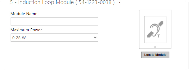 |
- Module Name – set the module name. The module name is used for induction loop event logging.
- Maximum Power – set the maximum transmission power for the induction loop antenna. A higher transmission power means a wider range, but less power for other intercom functions. The convenient default value is 0.25 W under normal circumstances.
Display Module Configuration
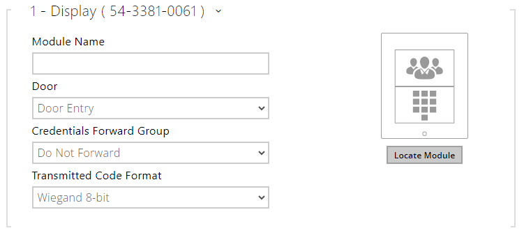 |
- Module Name – set the module name for logging the display events.
- Door – set the reader direction (Door Entry, Door Exit) for the Attendance system purposes.
- Credentials Forward Group – set the group to which all the received user access codes will be resent.
- Transmitted Code Format – select a 4bit or 8bit (higher security) format for the codes to be transmitted.
Fingerprint Reader Module Configuration
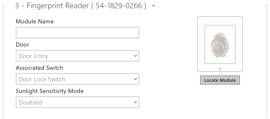 |
- Module Name – set the module name for logging events from the Fingerprint reader.
- Door – set the reader direction (Arrival, Departure) for the Attendance system purposes.
- Associated Switch – set the switch to be activated after user authentication via this module. If you set Door Lock Switch, the authentication rules specified in Hardware / Door will be used.
- Sunlight Sensivity Mode – enable this parameter to prevent erroneous behavior of the reader if exposed to direct sunlight. Restart the device to change the setting. The mode may reduce the reading sensitivity.
Caution
- Whenever the fingerprint reader is disconnected, the User fingerprints will be hidden in the user profile after restart. This section displays how many user fingerprints have been uploaded to the intercom memory. Once a fingerprint reader is reconnected, the User fingerprints will be displayed again.
Touch Keypad Configuration
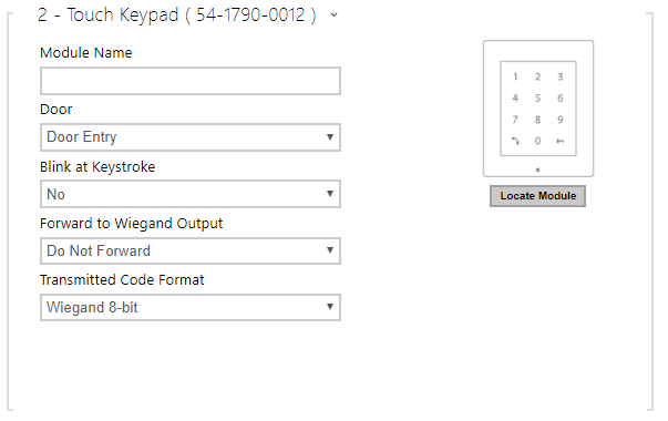 |
- Module Name – set the module name for logging events from the touch keypad.
- Door – set the reader direction (Door Entry, Door Exit) for the Attendance system purposes.
- Blink at Keystroke – set keystroke light signaling for noisy environments where acoustic signals are difficult to hear.
- Forward to Wiegand Output – set a group of Wiegand outputs to which all pressed keys are to be forwarded.
- Transmitted Code Format – select a 4bit or 8bit (higher security) format for the codes to be transmitted.
Touch Keypad & 125 kHz, 13.56 MHz RFID Reader Configuration
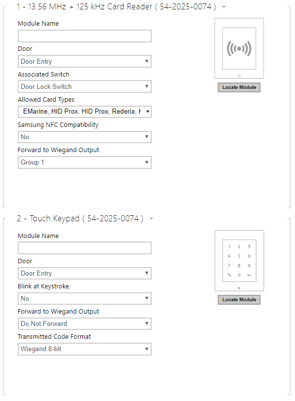 |
- Module Name – set the module name for card reader logging purposes.
- Door – set the reader direction (Not specified, Arrival, Departure) for the Attendance system purposes.
- Associated Switch – set the switch to be activated after user authentication via this module. If you set Door Lock Switch, the authentication rules specified in Hardware / Door will be used.
- Allowed Card Types – set the type of a card to be accepted by the card reader. If possible, choose one card type and disable the others. Some card type combinations are not supported as they may negatively affect the data reading quality.
- Samsung NFC Compatibility – enable NFC compatibility with the Samsung phones.
- Forward to Wiegand Output – set a group of Wiegand outputs to which all the received RFID card IDs will be resent.
Touch keypad (serial number)
- Module Name – set the module name for logging events from the touch keypad module.
- Door – set the reader direction (Door Entry, Door Exit) for the Attendance system purposes.
- Blink at Keystroke – set keystroke light signaling for noisy environments where acoustic signals are difficult to hear.
- Forward to Wiegand Output – set a group of Wiegand outputs to which all pressed keys are to be forwarded.
- Transmitted Code Format – select a 4bit or 8bit (higher security) format for the codes to be transmitted.
Bluetooth & 125 kHz, 13.56 MHz RFID Reader Configuration / 2N IP Style
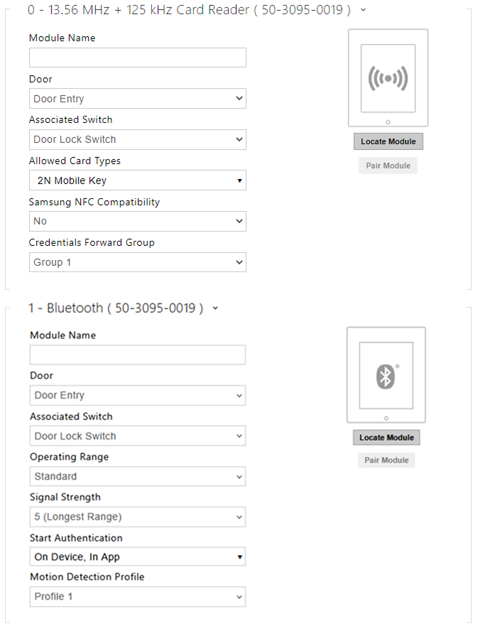 |
- Module Name – set the module name for card reader logging purposes.
- Door – set the reader direction (Arrival, Departure) for the Attendance system purposes.
- Associated Switch – set the switch to be activated after user authentication via this module. If you set Door Lock Switch, the authentication rules specified in Hardware / Door will be used.
- Allowed Card Types –set the type of a card to be accepted by the card reader. If possible, choose one card type and disable the others. Some card type combinations are not supported as they may negatively affect the data reading quality.
- RFID Symbol Backlight (for IP Style only) – switch on/off the RFID symbol backlight on the device.
- Samsung NFC Compatibility – enable NFC compatibility with the Samsung phones.
- Forward to Wiegand Output – set a group of Wiegand outputs to which all the received RFID card IDs will be resent.
Bluetooth (serial number)
- Module Name – set the module name for logging events from the Bluetooth module.
- Door – set the reader direction (Not specified, Arrival, Departure) for the Attendance system purposes.
- Associated Switch – set the switch to be activated after user authentication via this module. If you set Door Lock Switch, the authentication rules specified in Hardware / Door will be used.
- Operating Range – Limited Operating Range mode reduces the operating distance to up to 5 m for Bluetooth signal.
- Signal Range – set the signal range (5 = maximum, 1 = minimum), i.e. the distance over which the Bluetooth module can communicate with a mobile phone. It is recommended that the actual signal range is tested while setting, as it is affected by a number of factors (installation layout, mobile phone type and position in particular).
- Start Authentication – set the authentication method for a mobile phone:
- In App – authentication has to be confirmed by tapping on an icon in the application running in a mobile phone.
- On Device – touch the card reader having a phone with paired My2N to confirm authentication.
- Via Motion Detection – authentication will be launched by motion detection via a phone with the paired My2N application.
- Motion Detection Profile – set the motion detection profile for the module authentication via a mobile phone.
Touch Keypad & Bluetooth & 125 kHz, 13.56 MHz, NFC RFID Reader
|
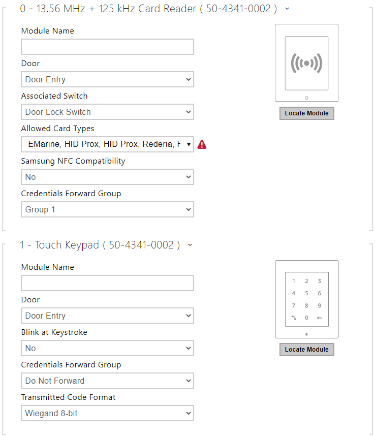
13.56 MHz (125 kHz) Card Reader (serial number)
- Module Name – set the module name for card reader logging purposes.
- Door – set the reader direction (Not specified, Arrival, Departure) for the Attendance system purposes.
- Associated Switch – set the switch to be activated after user authentication via this module. If you set Door Lock Switch, the authentication rules specified in Hardware / Door will be used.
- Allowed Card Types – set the type of a card to be accepted by the card reader. If possible, choose one card type and disable the others. Some card type combinations are not supported as they may negatively affect the data reading quality.
- Samsung NFC Compatibility – enable NFC compatibility with the Samsung phones.
- Credentials Forward Group – allows you to set a group to which all received user access codes will be forwarded.
Touch Keypad (serial number)
- Module Name – set the module name for logging events from the touch keypad module.
- Door – set the reader direction (Door Entry, Door Exit) for the Attendance system purposes.
- Blink at Keystroke – set keystroke light signalling for noisy environments where acoustic signals are difficult to hear.
- Credentials Forward Group – set the group to which all the received user access codes will be resent.
- Transmitted Code Format – select a 4bit or 8bit (higher security) format for the codes to be transmitted.
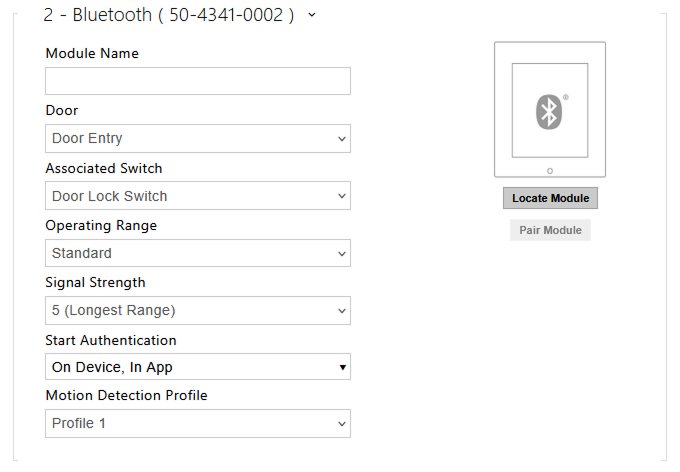
Bluetooth (serial number)
- Module Name – set the module name for logging events from the Bluetooth module.
- Door – set the reader direction (Not specified, Arrival, Departure) for the Attendance system purposes.
- Associated Switch – set the switch to be activated after user authentication via this module. If you set Door Lock Switch, the authentication rules specified in Hardware / Door will be used.
- Operating Range – Limited Operating Range mode reduces the operating distance to up to 5 m for Bluetooth signal.
- Signal Strength – set the signal range (5 = maximum, 1 = minimum), i.e. the distance over which the Bluetooth module can communicate with a mobile phone. It is recommended that the actual signal range is tested while setting, as it is affected by a number of factors (installation layout, mobile phone type and position in particular).
- Start Authentication – set the authentication method for a mobile phone:
- In App – authentication has to be confirmed by tapping on an icon in the application running in a mobile phone.
- On Device – touch the card reader having a phone with paired My2N to confirm authentication.
- Via Motion Detection – authentication will be launched by motion detection via a phone with the paired My2N application.
- Motion Detection Profile – set the motion detection profile for the module authentication via a mobile phone.