ELAN
| Manufacturer: | 2N Telekomunikace a.s. |
|---|---|
| Model: | 2N® IP Verso |
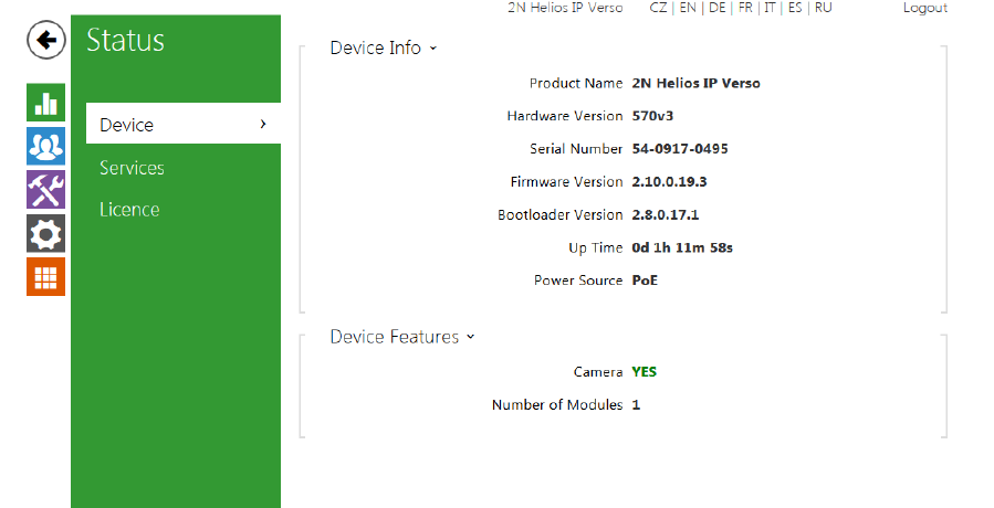
| Comments: | Firmware 2.10.0.19.3, Bootloader 2.8.0.17.1, Hardware Version 570v3 Minimum Core Module 7.2.xxx |
| Document Revision Date: | 11/24/2015 |
OVERVIEW AND SUPPORTED FEATURES
The 2N® IP Verso SIP Door Station is an SIP Door Station solution with an integrated video camera for monitoring door activity. ELAN g! integration with the station supports the following features:
1. Paging- When the “Call” button is pressed on the Door Station, it will call all appropriate Intercom Stations based on the House Mode of the g! System
2. 2 Way Calls- A user at an Intercom Station can converse with the person who pressed the “Call” button
3. Video Monitoring- The camera in the Door Station may be accessed from any Intercom Station to view the caller
4. Relay/Door Strike Actuation through the UI- As of the release of g! 7.3, Relays and Door Strikes are supported through the Door Station Interface
5. Relay/Door Strike Actuation through Event Mapper- As of the release of g! 7.3, Relays and Door Strikes are supported through the Event Mapper
INTEGRATION REQUIREMENTS
The 2N® IP Verso Door Station requires a single CAT5 Ethernet connection to the same network to which the g! Intercom Controller is attached. The station may be powered either using PoE or with a separate 12VDC power supply:
Pull the CAT5 cable from the door station location to the Network Switch or Router
Terminate both ends of the cable
Test the cable to ensure proper performance
Connect the Door Station; ensure that it powers up.
COMPONENET SETUP
- Prior to setting up the SIP component of the Door Station, you will need to enable the SIP Server in the g! Controller. Please see the Intercom Integration Note for details on this configuration.
SIP VOIP:
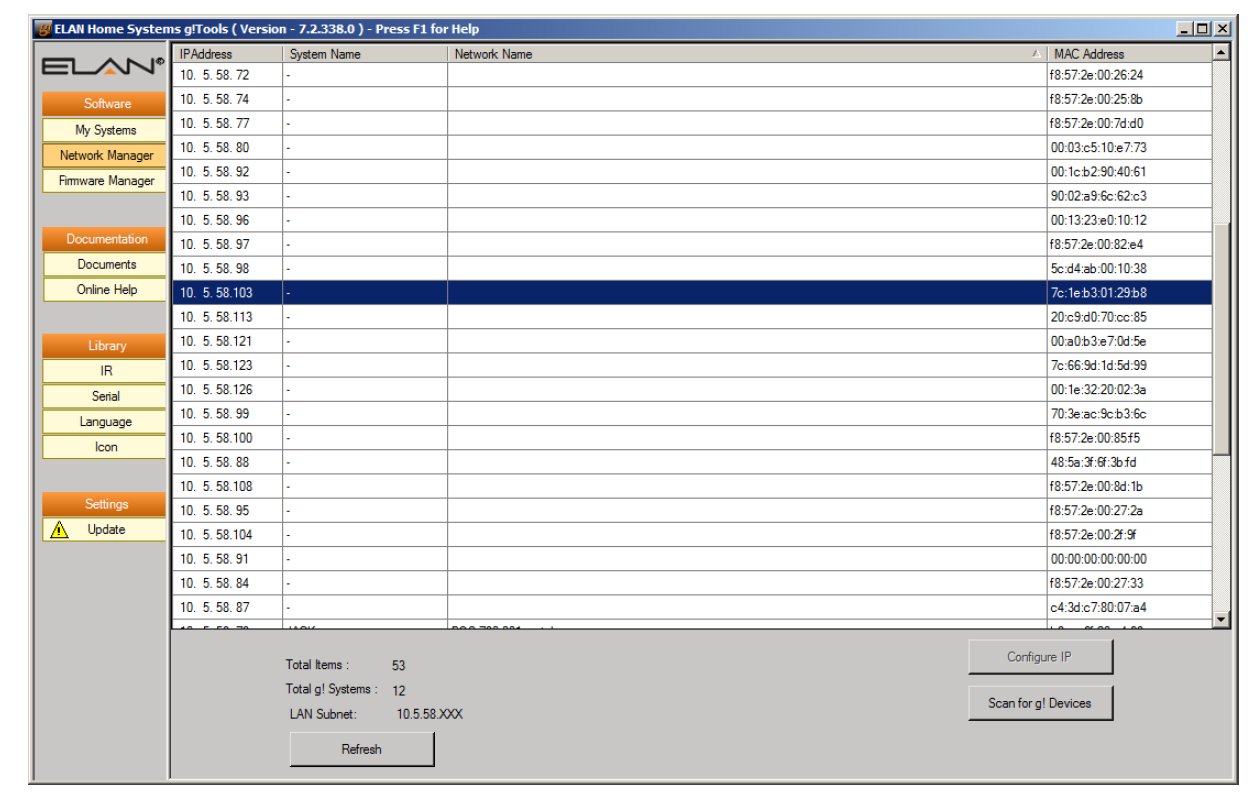
1. Determine the IP Address of the 2N Door Station. This can be done by using the Network Manager utility in g! Tools and finding the MAC Address of the unit in the list. The MAC Address is on a sticker on the back of the unit:
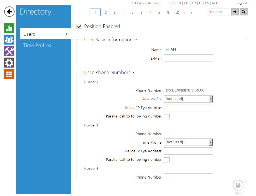
b. Under User Basic Information-> Name, type ELAN (Note you may use any name you like here). The E-Mail field may be left blank
c. Under User Phone Numbers-> Number 1-> Phone Number type sip:ELAN@x.x.x.x, where “x.x.x.x” is the IP Address of the g! Controller. Note that you may use any user name you wish in place of ELAN.
d. All other fields on this screen may be left blank
4. Select the “Services” Icon on the left to access the Services screen
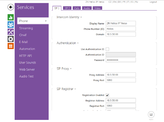
i. Set the Phone Number- this is actually the “Name” with which the device will populate in the SIP server- it does NOT have to be an actual number. Please use a descriptive name here such as “Front Door”
ii. Set the Domain to the IP Address of the g! Controller
b. On the SIP 1 Tab-> SIP Proxy
i. Set the Proxy Address to the IP Address of the g! Controller
ii. Ensure the Proxy Port is set to 5060
c. On the SIP 1 Tab-> SIP Registrar
i. Check the “Registration Enabled” box
ii. Set the Registrar Address to the IP Address of the g! Controller
iii. Ensure the Registrar Port is set to 5060
iv. Leave the Registration Expires time set to default
d. On the Audio Tab
i. Uncheck G.722
ii. Make G.711 (PCMU) the first choice
G! CONFIGURATION DETAILS
CONFIGURE THE DOOR STATION
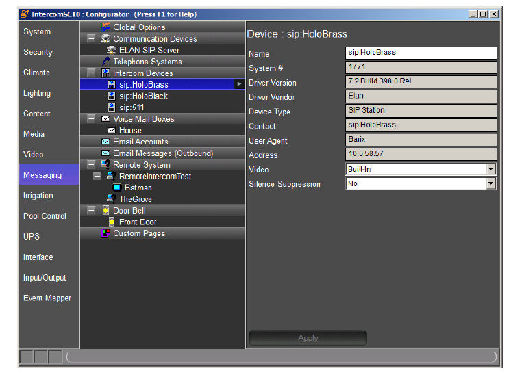
The Door Station should connect to the g! Controller as soon as it is provided the IP Address of the SIP server. When it connects, it will automatically populate under the Door Station heading on the Messaging tab in Configurator:
CONFIGURE THE RELAYS FOR THE DOOR STATION
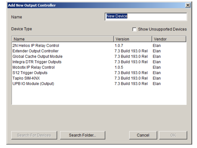
As of the release of g! 7.3, the relays on the 2N® IP Verso may be added into Configurator in order to display a button in the UI, allowing the end user to press a button in the interface to open the door after verifying to whom they are speaking. Before this feature may be used, the Relays must be added on the Input/Output tab. In the “Relay Outputs” section, right click and select “Add New Output Controller”:
Once the relays are added to the Input/Output tab, it is possible to use them in the Event Mapper. In order to get the relays to appear on the Door Station User Inte
Once the relays are added to the Input/Output tab, it is possible to use them in the Event Mapper. In order to get the relays to appear on the Door Station User Interface, further configuration is required in the Messaging tab.
ADD RELAYS TO THE USER INTERFACE (UI)
Once the relays have been configured on the Input/Output tab, they can be added to the Door Station UI from the Messaging tab. Select the correct Door Station from the Tree and expand the list by clicking on the “+” sign next to the heading. Select the “Options” tree item and you will be able to assign the relays to buttons in the interface. Up to two buttons per door station may be enabled in the Door Station UI (Labeled as “Output 1” and “Output 2” in Configurator), any other relays may be actuated with the Event Mapper. Use the Dropdown labeled “Output” to assign the correct relay. The Interface button will be populated with the Name in the Output 1 Name field. The type of relay (Toggle or Momentary) may be selected from the “Output Type” dropdown.
Common Mistakes
1. No Video. If there is no video for the door station in the viewer, ensure that the Video drop-down for the Door Station on the Messaging tab has the correct camera selected.
2. Door Station not populating in the Viewer. Make sure that the Door Station has populated on the Messaging tab in Configurator. Check the settings in the Door Station Web GUI to make sure the g! Controller is assigned as the SIP server.
3. No Page signal sent when button is pressed. Ensure that the Dial Plans are set up correctly and the system is in the correct System Mode for the Dial Plan. See the Intercom Integration Note for details on setting up Dial Plans
4. No audio at door station during a call. Under Settings-> Audio, ensure that G.722 is unchecked, and G.711 (PCMU) is the first choice.

