2.14 Evacuation Audio Unit – Floors
Description of Use
2N Lift8 Audio Unit, Landing (Evac.) (Part No. 918618EE) is an audio unit designed for installation at the evacuation elevator on the floors. The audio units provide connection with the control center for evacuation coordination.
Press the button (for more than 3 seconds) to set up a call to the control center. Once the call is received by the control center, the connection is established. The call is hands-free and cannot be terminated from the audio unit.
The call setup is signaled by the Fireman audio unit LED.
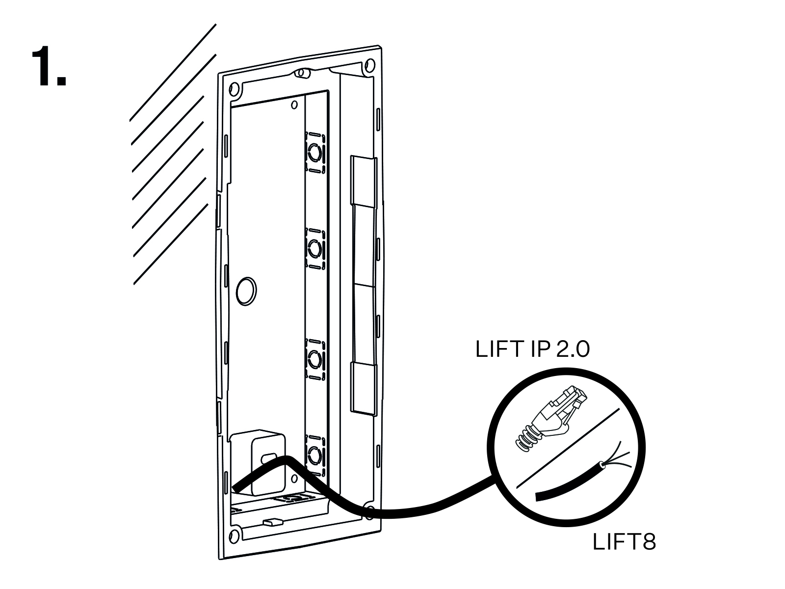
Mechanical Installation
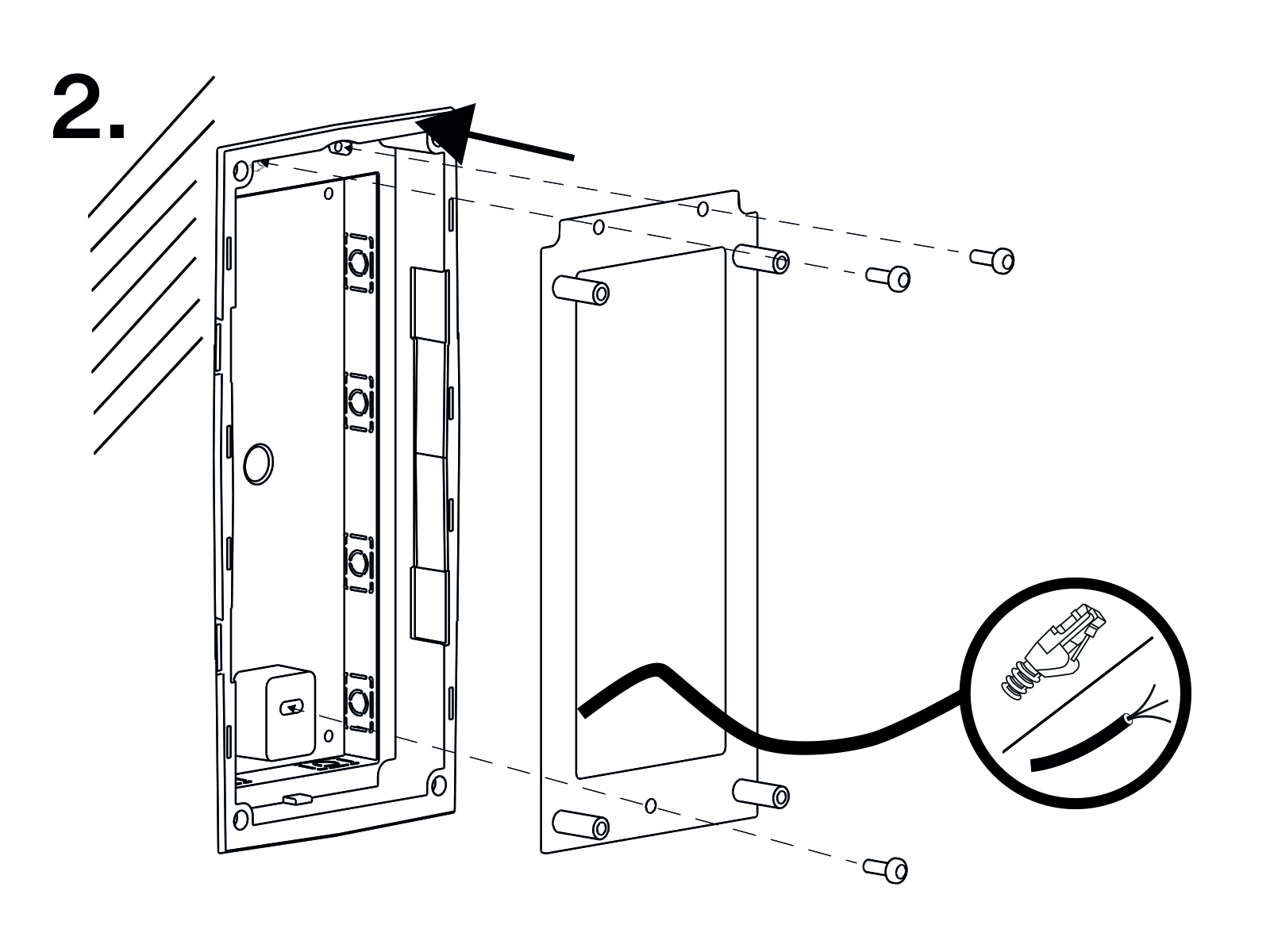
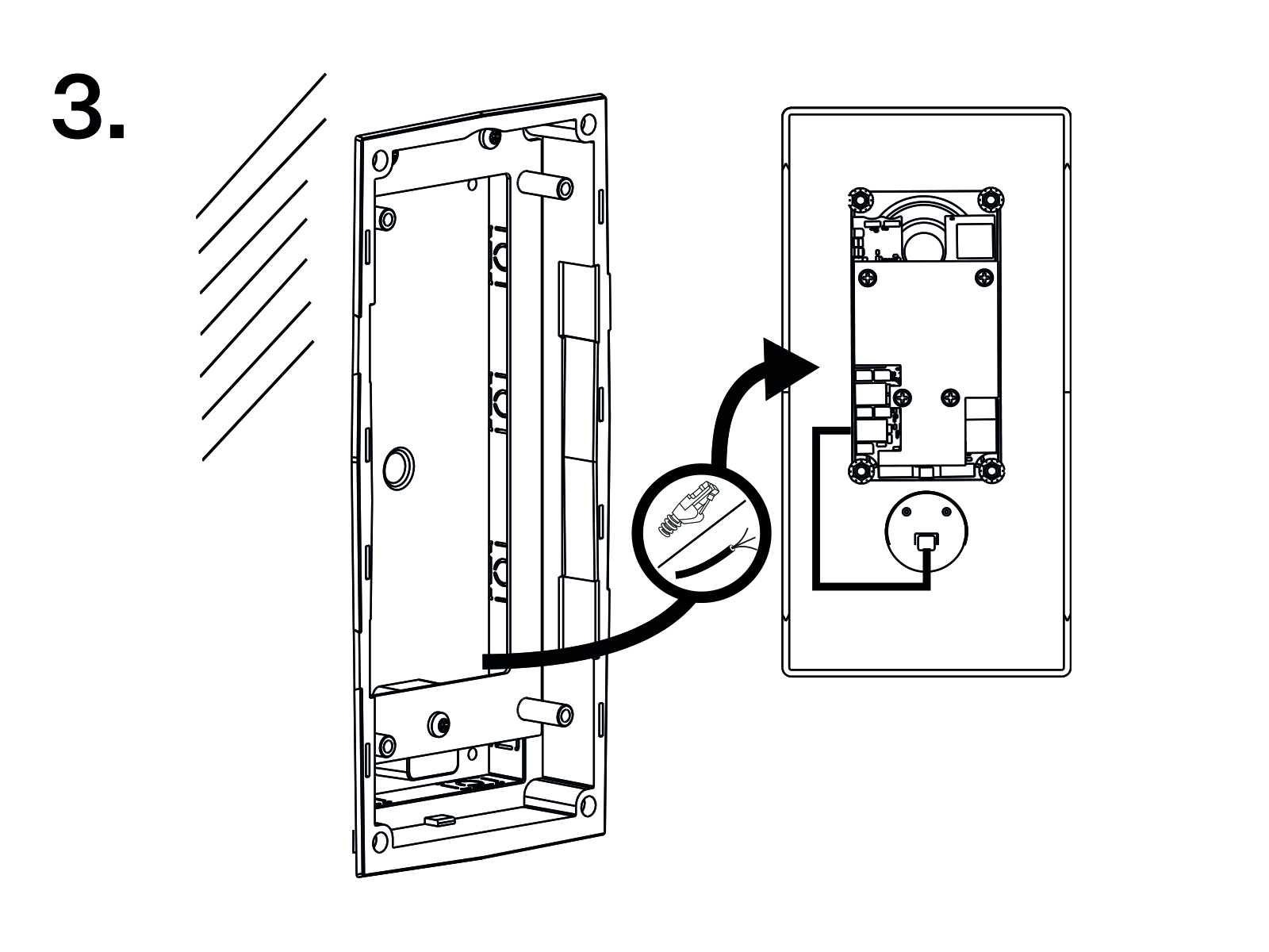
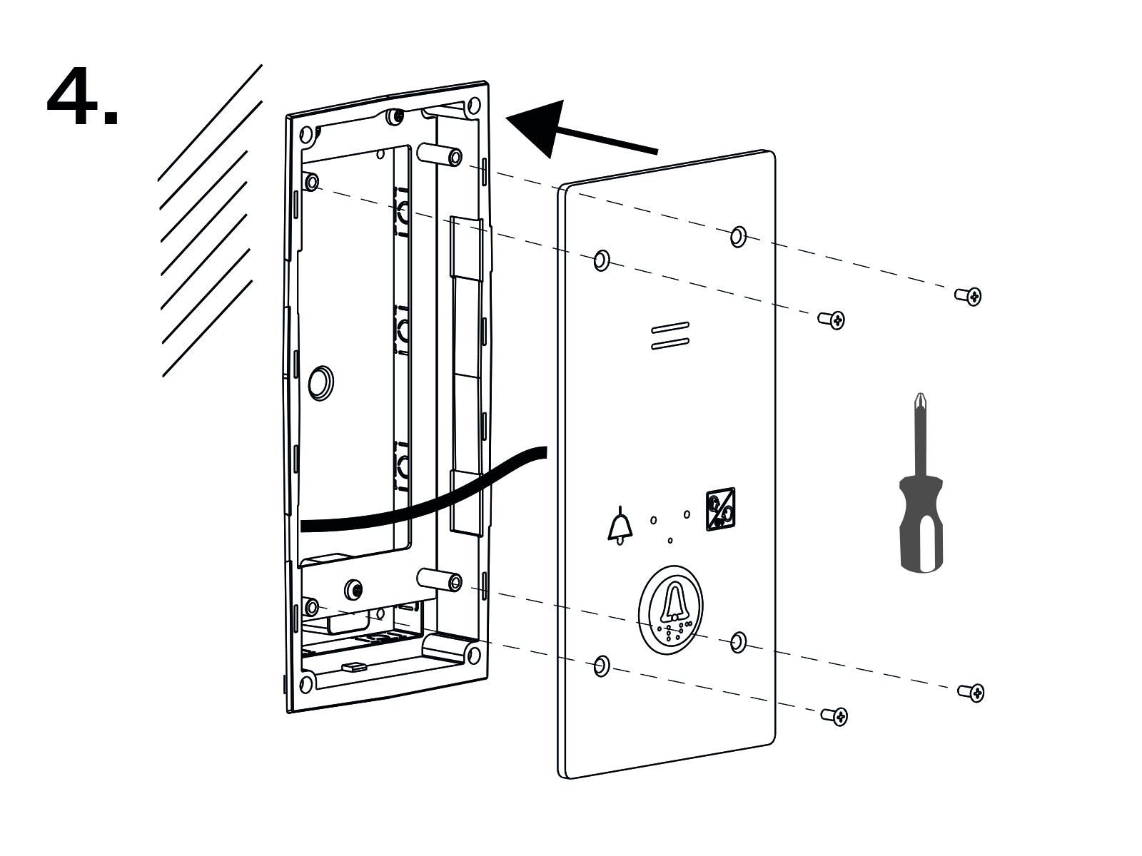
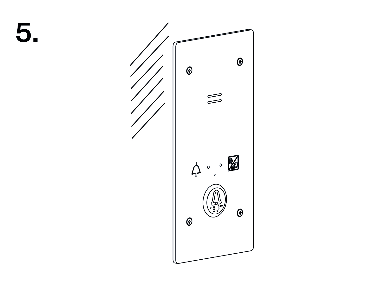
Electric Installation
Description of Terminals, Connectors and Jumpers

Terminals | Connectors | ||
|---|---|---|---|
1 | Audio unit bus | 7 | Green LED |
2 | Unconnected (external button, voltage activation) | 8 | Yellow LED |
3 | Unconnected (external button, contact activation) | 9 | Unconnected |
4 | Unconnected | 10 | Induction loop connector |
5 | Unconnected | 11 | Speaker connector |
6 | Unconnected | 13 | Servicing connect |
Configuration jumpers | Two LED signal lamps (other side) | ||
12 | Addressing audio unit | Green | Connection established |
Yellow | Active call | ||
Bus Connection
- Pull the terminal out of connector 1 – Audio units bus.
- Connect the bus audio units wires.
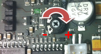
- Replace the terminal to connector 1. Mind the polarity. Proper polarity (+ -) is shown on the cover of audio unit.
Warning
- The audio unit is intended for 2N Lift8 audio unit bus connection exclusively. Do not connect it to other wires to avoid its damage or destruction.
Caution
- The audio unit is powered via a 2-wire bus. Disconnection of these wires results in the audio unit switch-off.
Addressing Audio Unit
Addressing the audio unit is crucial for a proper system functioning. Up to 8 audio units can be connected to one splitter. Each audio unit must be addressed to a unique position within the splitter.
Procedure
- Pre-configure the jumper on the configuration jumper 12.
- The first 4 pins serve for setting the location of the audio unit.
- If there is poor access to the pins, it is possible to remove the covers of the electronics.
- Slightly loosen the four screws and shift the cover upwards.
- Now you can removed the cover.
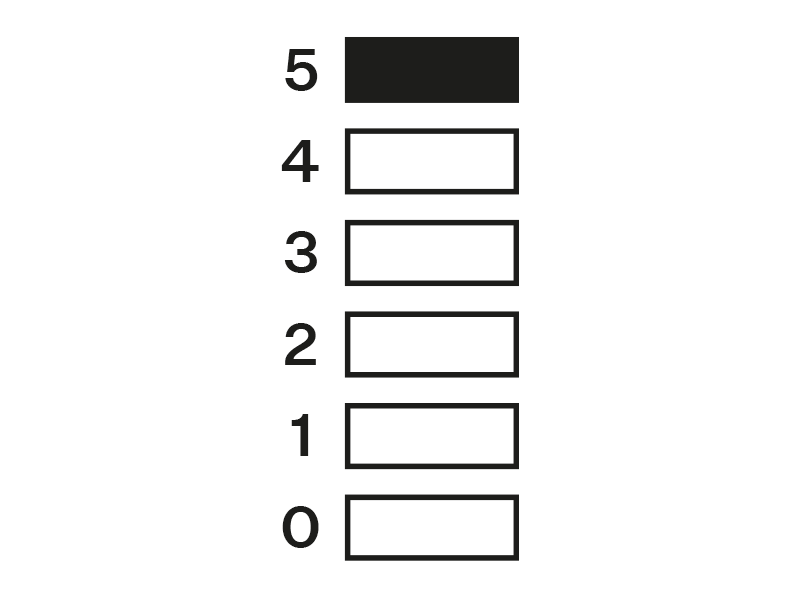
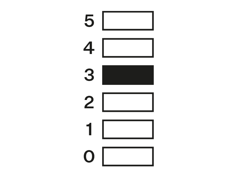
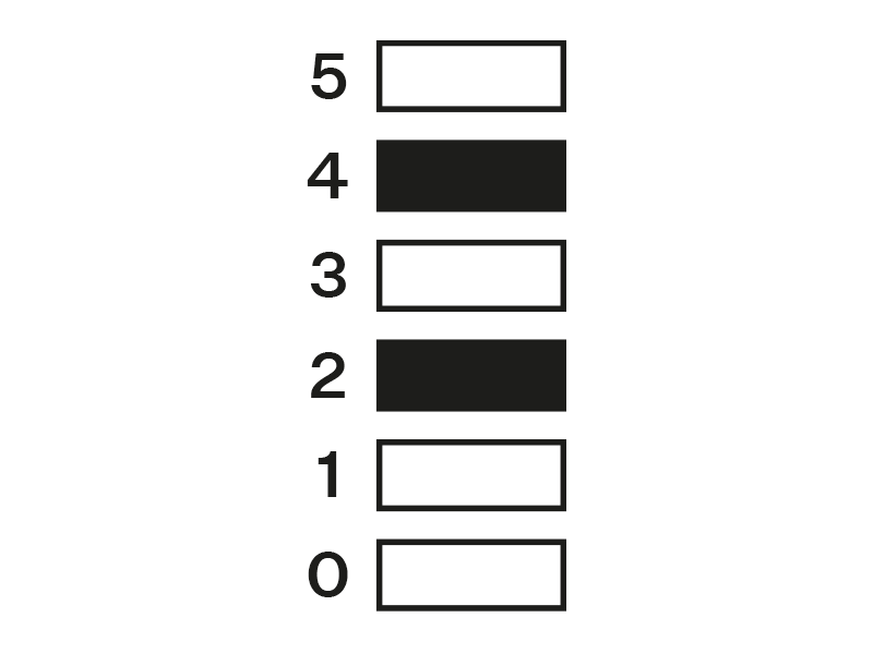
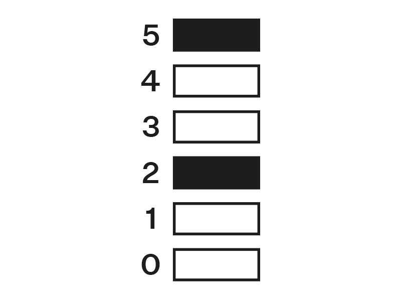
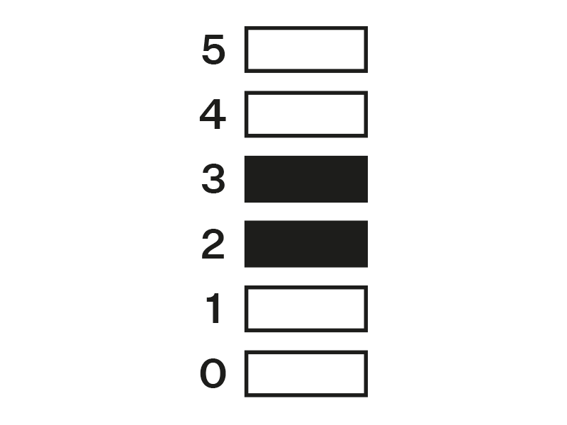
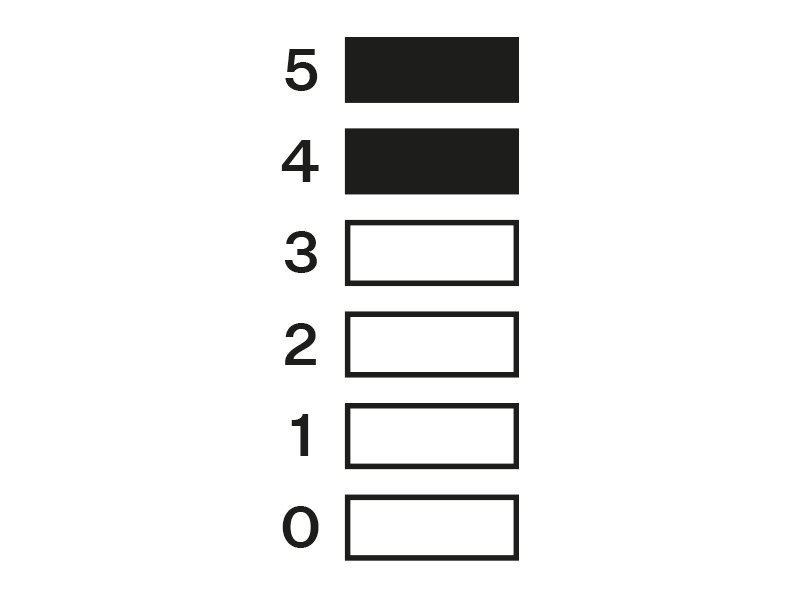
Set the audio unit position by placing the jumper according to the following table:
1st position
2nd position
3rd position
4th position
5th position
6th position
7th position
8th position
- If you have removed the cover, put it back in the original position and tighten the screw.
Within the entire system, the audio units are numbered by individual splitters as follows:
Splitter 1 (CU) | Splitter 2 | Splitter 3 | Splitter 4 | Splitter 5 | Splitter 6 | Splitter 7 | Splitter 8 | |
1st - 8th position | 1–8 | 9-16 | 17-24 | 25-32 | 33-40 | 41-48 | 49-56 | 57-64 |
Volume Configuration
Slightly loosen the four screws and shift the cover downwards. Now you can remove the cover. Use the trimmer located in the bottom part of the electronics to set the required volume level (see the figure).