5.3 Control Panel Use
The main purpose of the application is to virtualise ports and facilitate connection to terminals. The application also provides comfortable administration and user management including assignment of terminal administration rights, thus allowing users to manage a high number of terminals from one site and be assigned small terminal groups for easier administration.
User Mode
Having singed in as the User, you get access to four items of the main menu only: Terminals, Connections, Virtual Ports and Settings. They are all you need for standard work with the terminals. You have been assigned to one of the groups by the Administrator and so you are allowed to view the terminals assigned to this group. See below for details on the menus.
Terminals
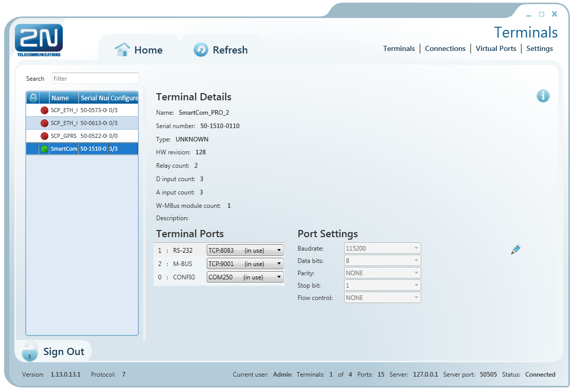 |
Figure: User Mode Terminals Menu
The Terminals menu displays the terminals assigned to the group you have the right to view.
A green dot before the terminal means that the terminal is on-line (connected to the server) and you can get connected to it. A red dot means that the terminal is off-line.
Click on a selected terminal to display the Terminal Details window to the right including the terminal name, serial number, hardware revision number and count of available relays and digital and analogue inputs. Notes are also displayed on each terminal if available.
If you are a User, you can select a virtual port for terminal connection. The Virtual ports can fully be administered by the User; refer to the Virtual Ports subsection below. If you select an unoccupied port, the port will be marked 'in use' signalling to the other users that the port is engaged in the configuration.
If you have the appropriate user right, you can also set communication parameters for the selected port including the transmission rate and other parameters even if the terminal is connected and used for data transmission. Select the parameters using the combo boxes and the changes will be effective the moment they are saved.
Click the Info button in on-line terminals to display details on the connected terminal, relay control and values measured on analogue and digital inputs.
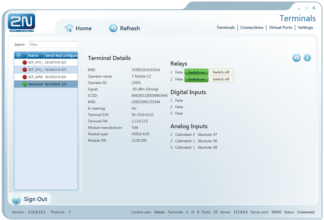 |
Figure: Terminals Menu Terminal Details
The Terminal Details menu includes the following data: GSM module IMEI
(International Mobile Equipment Identity), name and number of the GSM provider with which your 2N® SmartCom PRO is registered, signal intensity in dBm,
ICCID (Integrated Circuit Card ID) and IMSI (International Mobile Subscriber Identity). The In roaming parameter indicates whether the SIM card is used in the roaming mode. Moreover, the 2N® SmartCom PRO terminal serial number and current firmware as well as information (firmware version, manufacturer and type) on the GSM module used are displayed.
You can switch the relay contacts in the Relays section. The Digital Inputs section displays the value currently measured at the input and transformed to a logic value (0 or 1) as calibrated. The Analogue Inputs section displays the values measured at analogue inputs. The Calibrated and Absolute parameters display the percentage against the calibrated range and the absolute value against the A/D converter range respectively.
Refer to Subss. 3.3 and 3.4 Input Circuits for more details on input circuit function and calibration.
 |
Figure: Terminal Time Synchronisation
The time setting supporting PRO and PRO ETH terminals also display the terminal time. Click Synchronise to set the same time value for the terminal as there is in the server.
Connections
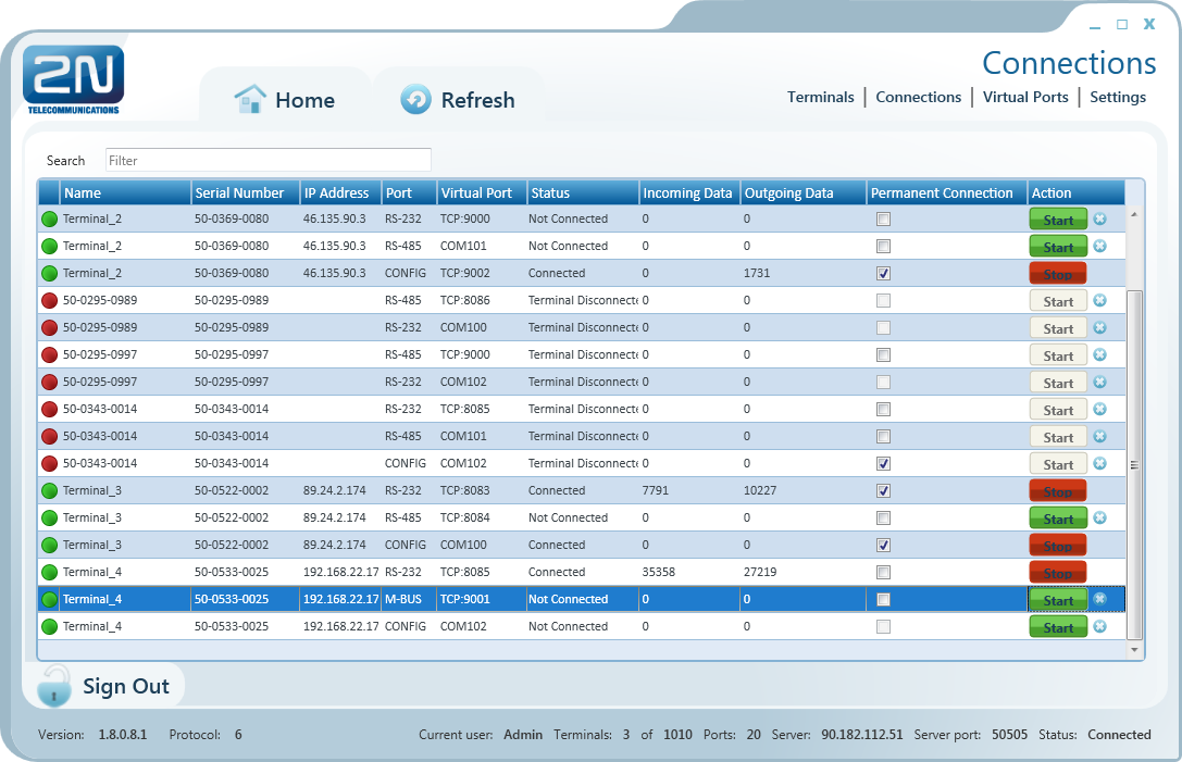 |
Figure: Connections Menu
The Connections menu contains a table showing the terminals that are assigned a virtual port. The table includes the terminal name, serial number, IP address and physical port to be connected to the selected virtual port. The Status field defines the current of the terminal:
- Not Connected – the terminal is on-line connected to the server and ready for virtual port connection.
- Connecting – the terminal - virtual port connection is in progress.
- Connected – the terminal has been successfully interconnected with the virtual port.
- Disconnecting – disconnection from the virtual port is in progress.
- Terminal Disconnected – the terminal is off-line, i.e. has been disconnected from the SC Server.
- Disconnect by other user – the terminal has been disconnected by another user (this means that the other user has interconnected its virtual port with this terminal).
- Error – an error occurred during connection or disconnection.
The Incoming and Outgoing Data fields display the amount of data transmitted in the given direction and are for information only. Check Permanent connection to enable automatic terminal connection to the virtual port upon the application start.
Press Start to interconnect the terminal with the virtual port. If one and the same port is used by multiple terminals, the other users will be unable to press Start until the first connection has been finished. Refer to the note below. Push Stop to terminate communication.
Note
- Although multiple terminals can be assigned to one virtual port, one terminal can only be assigned to one virtual port for connection.
In case another user is connected to the terminal, the Start button has an orange background colour. You can push the button to disconnect the original user and connect the terminal to your virtual port.
Use the cross to remove the selected row from the table, thus cancelling interconnection between the virtual port of the application and the terminal physical port easily.
Virtual Ports
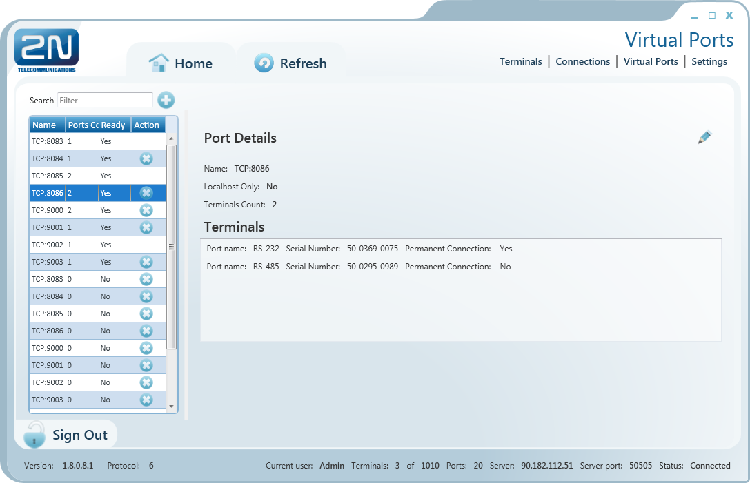 |
Figure: Virtual Ports Menu
Administer virtual ports using the Virtual Ports menu. Every user can use this menu as these settings only relate to the PC with which the user is working. This means that where more PCs are used, the user must create virtual ports for each of them. This, however, applies to serial ports only; virtual ports are transferable to other PCs. This option, however, can be disabled in the configuration – LocalHost Only. The listing of the terminals that are assigned the given virtual port displays the physical port to which the virtual port is assigned, serial number and Autoconnect setting from the Connections menu.
Add Virtual TCP Port
To add a virtual TCP port, select Add Port and enter the port number. Also, select the Allow local host only option to enable the port use for the current PC only. Finally, click Create.
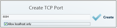 |
Figure: Add TCP Port
Add Virtual COM Port
A virtual COM port is created similarly as instructed above. Just select a port and click Create to make the com0com driver install the selected port into the PC.
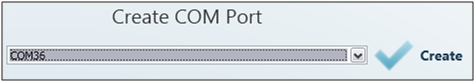 |
Figure: Add COM Port
Once installed in the PC, the COM port needs to be activated. Although the port has been added to the Virtual ports table, the Ready item shows NO. Therefore, click on this table row to view the port details and the Refresh button. Push the button to change the port status from Ready – NO to Ready – YES. Now the port can be used normally.
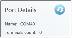 |
Figure: Refresh Button
Settings
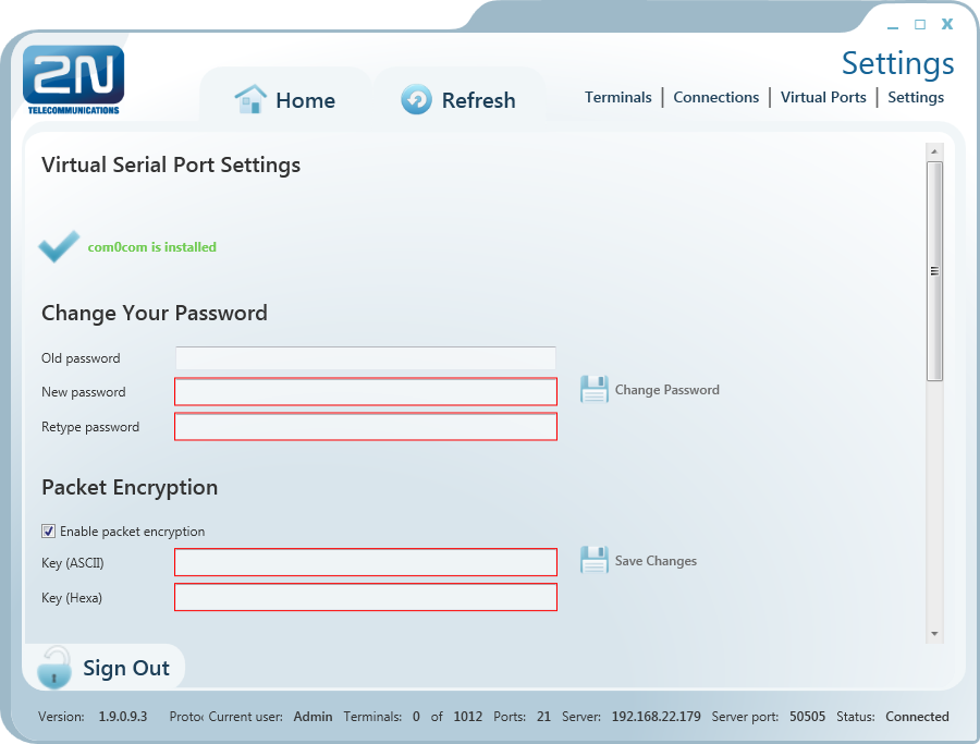 |
Figure: Settings Menu
You can change the user password in the Settings menu. Enter the old password and then the new one. The minimum password length and correctness is checked by the parameter limits. Save the setting using the Change password button.
The menu also displays the installation states of the virtual serial port drivers. If no drivers have been installed, you cannot use or add serial ports in the Virtual ports menu. If the com0com driver is not installed, the 'com0com is not installed' message gets displayed as shown in the figure. You can install drivers for 32 and 64-bit systems too. If the installation has been successful, the ‘com0com is installed’ message is displayed automatically.
Caution
- You need the Admin rights for the PC used for com0com installation. If you do not have such rights currently, the installation will offer you an Admin login option.
Note
- The installation requires 0.5 MB of free disk space at least.
The menu also includes encryption key settings for server communication, like in the sign-in window. Tick the checkbox to enable packet encryption. Enter the selected key into the Key field and save the setting. The setting will not be applied until you sign out. Moreover, you can set the configuration export/import options. Select the Virtual ports, Connections and/or Automatic connections in the Export Settings item to transfer your configuration to another PC. Choose the export destination and press Export to execute the operation.
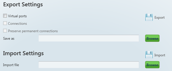 |
Setting Export / Import
To import your configuration, sign in as the user to which the settings shall be imported. Make sure that this user is identical with the user from which export was made to create a correct configuration file. Now you can load the new configuration onto any account. Select the file to be imported and press Import to import the data. The change will be applied when the user signs out and in.
Moreover, you can set Automatic sign-in in this menu. If you enable this function, the application will automatically log in to the server within a preset time interval. If you interrupt auto login in this interval, you can change the login data and sign in as another user or to another server.
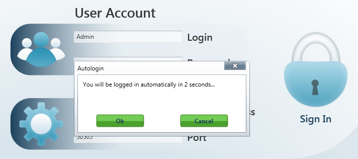 |
Auto Login
Caution
- By interrupting automatic login you also disable the Allow automatic login parameter. Thus, you will have to re-enable it to use auto login again.
The application Logging checkbox helps you debug the application or just record server communication.
The files are automatically split after reaching 10MB.
Admin Mode
The Admin user has access to all User mode menus plus the user and terminal administering and server setting menus. The Admin mode menu includes the Users, Groups, Links, Terminals, Server Settings and Firmware Management menus. See the subsections below for details.
Users
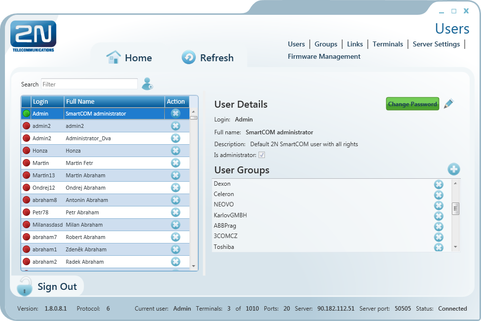 |
Figure: Users Menu
The Users menu is used for user administration. The list of users is on the left. A green dot before the user name means that the user is on-line (logged-in to the
2N® SmartCom Server). A red dot means that the user is off-line (logged out).
Click on the user to display the User Details including the full name, login, notes and Admin flag if available. By clicking on Change password, the Administrator can change any user password without knowing the original one. This is mainly useful for those users who forget their passwords. Click Edit to change the user details.
The User Groups menu contains the user groups to which the user is assigned. Click Add and select an item from the list to create a new group. Push Remove to remove a group from the list.
Add User
Push the Add user button next to the filter setting. You will be asked to complete the login, full user name and password. Being crucial to a proper function, these parameters are limited and checked while entering: the name and login may not be duplicated in the configuration. You will be notified of duplication if any. You can also add a note and/or the Admin mode to the user by ticking of Is Administrator. Click Create to create a new user.
User Groups
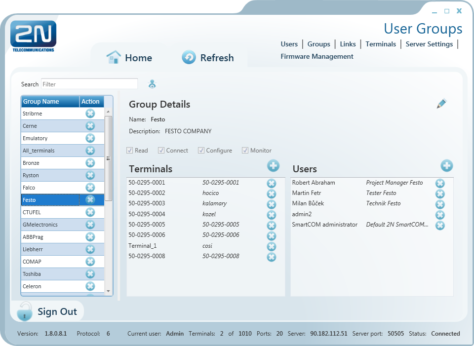 |
Figure: User Groups Menu
The User Groups menu helps you assign users and terminals to groups. As it is unnecessary for all users to view and manage all terminals, you can create small user groups for terminal data reading and administering.
Click a group to display the Group Details including the full group name, notes if any and rights assigned to the group. Click Edit to change these parameters.
There are 4 categories of group rights.
- Read – users with the Read right may view the terminals and monitor their states without being able to configure or connect to them.
- Connect – users with the Connect right may view and also connect to the terminals via the Connections menu.
- Configure – users with the Configure right have the advantages of the two user groups above and, moreover, may configure the communication parameters for terminal ports.
- Monitor – not implemented yet. Prepared for future use.
Use the Terminals menu to add/remove the terminals that are viewed by the users assigned to this group. Click Add and select an item from the list to add a terminal. Click Remove to remove a terminal from the list.
The Users menu includes a list of users assigned to this group. Click Add and select an item from the list to add a user. Click Remove to remove a user from the list.
Add Group
Click the Add group button next to the filter setting to add a group. You will be asked to complete the group name and rights. Being crucial to a proper function, these parameters are limited and checked while entering: the name may not be duplicated in the configuration. You will be notified of duplication if any. You can also add a note to the group. Click Create to create a new group.
Links
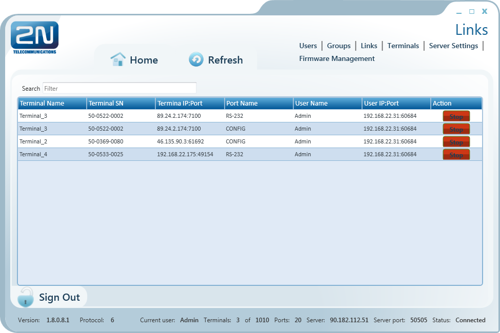 |
Figure: Links Menu
The Links menu displays the currently connected terminals and users. The Administrator can supervise and disconnect them if necessary. The table includes the terminal serial number, IP address and port, the user currently working with the terminal including its active IP address and port. Find the Stop button in the Action field.
Tip
- The Stop button is used for unconditional disconnection of a terminal from the virtual ports regardless of the transmission state.
Terminals
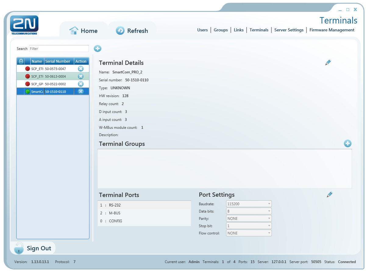 |
Figure: Admin Mode Menu
The Terminals menu in the Admin mode is similar to that in the User mode but is extended by group assignment, terminal adding and terminal editing options.
A green dot before the terminal means that the terminal is on-line (connected to the server) and you can get connected to it. A red dot means that the terminal is off-line.
Click on a selected terminal to display the Terminal Details window to the right including the terminal name, serial number, type (basic/PRO/PRO ETH) hardware revision number and count of available relays and digital and analogue inputs. Notes are also displayed on each terminal if available. Click on Edit to change the terminal details.
Specify a group in the Terminal Groups in which the selected terminal shall be visible (i.e. which group shall be allowed to use this terminal). Click Add to add a group. Click Remove to remove a group from the list.
You can also set communication for the RS 232 and RS 485/M-BUS ports and change the transmission rate and other parameters even if the terminal is connected and involved in data transmission. Select the parameters using the combo boxes and the changes will become effective when saved.
Add Terminal
Click on Add terminal next to the filter to create a new terminal.
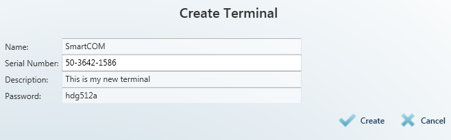 |
Figure:Create Terminal
To add a terminal, enter the terminal name, serial number and password. Being crucial for a proper function, these parameters are limited and checked while entering: the name and serial number may not be duplicated in the configuration. You will be notified of duplication if any. Click Create to create a new terminal.
Server Settings
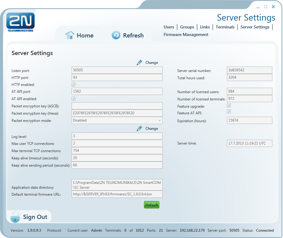 |
Figure: Server Settings Menu
The Server Settings menu contains the 2N® SmartComServer settings. The menu has three parts.
The first menu part affects the server function directly and any change may lead to restart and subsequent disabling of the other users’ work. Set the listening port and http port and enable the http daemon here. The user AT API settings are available here too. Set the port for API connection and communication. There is also a button for you to enable/disable the API. Futhermore, set packet encryption for the server: enter ASCII characters, which will automatically be translated into hexa for later server settings. The key length is 32 hexa / 16 ASCII characters. Or, you can enter hexa characters and the ASCII field will not be applied. See the figure above. Set the encryption mode in the Packet encryption mode parameter. There are three options.
- DISABLED – 2N® SmartCom Server does not encrypt any data.
- OPTIONAL – 2N® SmartCom Server encrypts data if the counterparty requires so.
- FORCED – 2N® SmartCom Serverencrypts all incoming and outgoing data.
Caution
- Important! A change of these parameters directly affects the server function. Remember the changed values for later use. For example, if you change the Listen Port, you have to enter a new port during login. If you forget it, you will have to reinstall the whole server!
- The web interface connection is only possible from the IP addresses from which the terminal/Control Panel was connected. Any other connecting attempts will be rejected to avoid server violation.
The other part does not affect the server function. You can modify the Log level setting, which is a digital value specifying how detailed the LOG file should be. The setting options are 1–5. The default value is 3.
Max user and Terminal TCP connections are automatically set to the highest possible value allowed by the licence. Enter the required count of connections to restrict the count if necessary. If you exceed the licence high, the application will automatically limit your selection to the upper limit allowed in the licence.
Also, set the Keep Alive packets. The default value is an optimum solution and need not be changed. Should problems occur with the NAT use on the application-server-terminal route, lower the time values. The Application Data Directory parameter shows the path to the directory where the 2N® SmartCom PRO Server saves the log files and is for information only.
Note
- The Application Data Directory shows the location of the server log files. Hence, it is only in the PC on which the Server is installed. You will not find this directory on the PC from which you launch the Control Panel and log in to the Server remotely!
Default Terminal Firmware URL is the address that can be used for terminal firmware upgrade. This firmware corresponds to and is fully compatible with the version of your Server and Control Panel.
Caution
- Remember to keep the firmware address format. Refer to the Server Settings menu for the currently valid address. If you enter this link into the terminal, the terminal will replace the sequence of characters '$(SERVER_IP)' with the address of the currently connected server.
The non-editable column to the right is the third section and includes information on the server to which you are connected such as serial number, licence hour counter, maximum user/terminal counts, upgrade enable/disable and AT API functions. It also shows the remaining server operation hours and the current server time.
Firmware Management
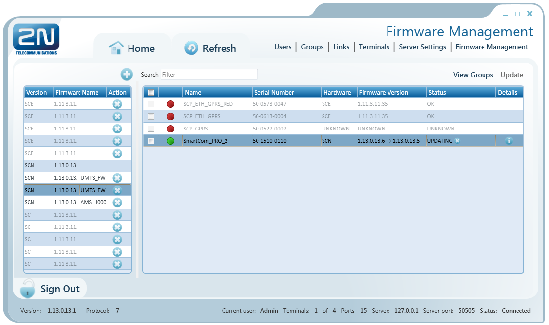 |
Figure: Firmware Management Menu
The Firmware Management menu is used for updating the 2N® SmartCom PRO terminal firmware via the 2N® SmartCom Server. Select a firmware version and tick off the terminal or group of terminals to be updated to activate the Update button and open the upgrade time setting window. Select a date and time value to schedule upgrade in advance.
Note
- The terminals that are off-line during the update will be updated as soon as they log in to the 2N® SmartCom Server.
There is a list of available FW versions in the left section of the window. Push the Add button to add a new firmware version to the list.
Caution
- Just one default firmware version identical with the 2N® SmartCOM Control Panel FW version is available after a new server installation. Add later firmware versions to the database if necessary.
- If you just upgrade the Server keeping the configuration instead of installing a new server, the firmware files will be retained. The firmware list will be identical with the original one plus a new default firmware version.
- If you select a SC or SCE terminal for upgrade, the firmware versions matching these HW types will only be listed to avoid invalid FW upgrade.
The right-hand window section displays a table including the list of all configured terminals or terminal groups (View Groups/View Terminals).
View Terminals
The table includes the following data: the checkbox helps select a terminal to be updated. The second column indicates whether the terminal is on-line or off-line. The terminal name, serial number and current firmware versions are available here too. An active or scheduled upgrade is indicated by 'original FW → new FW'. The Status field defines the state of the terminal updating process.
- OK – update completed, terminal ready for work.
- UPDATING – update in progress.
- ERROR – update error.
- UNKNOWN – terminal disconnected (FW version unknown).
View Groups
The table only includes group names and offers checkboxes for selection. Select a group and push Update to update all the terminals assigned to the selected group. Go back to View Terminals to display the update states for all the terminals.
Caution
- Remember to select the firmware version and one terminal/group at least to activate the Update button. Otherwise, Update will not be enabled.
- Tick off the checkbox in the table header to select all table items, i.e. all available terminals and/or terminal groups.
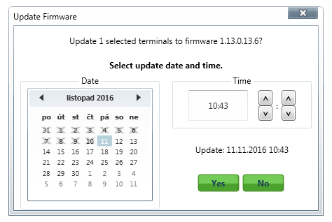 |
Firmware Update
Scheduled Terminal Update
Click Update to open a new window for you to schedule the upgrading date and time for the selected terminals. Push Yes to execute update immediately. As the current system time is running on the server, the updating procedure will start immediately. To execute update later, set the required date and time. The update will start automatically on the selected day and at the selected time.
Note
- There is a server limitation as to the count of terminals for updating. The purpose of this limitation is to protect the server and keep the required rate. If you want to update more terminals than 10 at the same time, the first 10 terminals will start updating at the specified time, the next 10 terminals will start updating in one minute and so on until all the selected terminals have been updated.
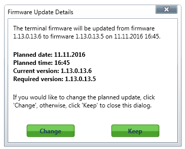 |
Figure: Firmware Update Details
Push the Info button in the Details column to open the Firmware update details including the upgrade date. Click Change to re-schedule the upgrade, or push Keep to retain the original setting and close the window.