3.3 Stand Installation
Alternatively, the device can be installed into a stand placed on a desk, for example. The stand is not included in the package.
Within installation preparations, take out the pre-prepared cabling, UTP cable, doorbell (twin) cable and power supply. Shorten the cables to the required length. Crimp the RJ-45 connector onto the UTP cable. Connect the doorbell twin cable together with the LAN connector to the connector.
Warning
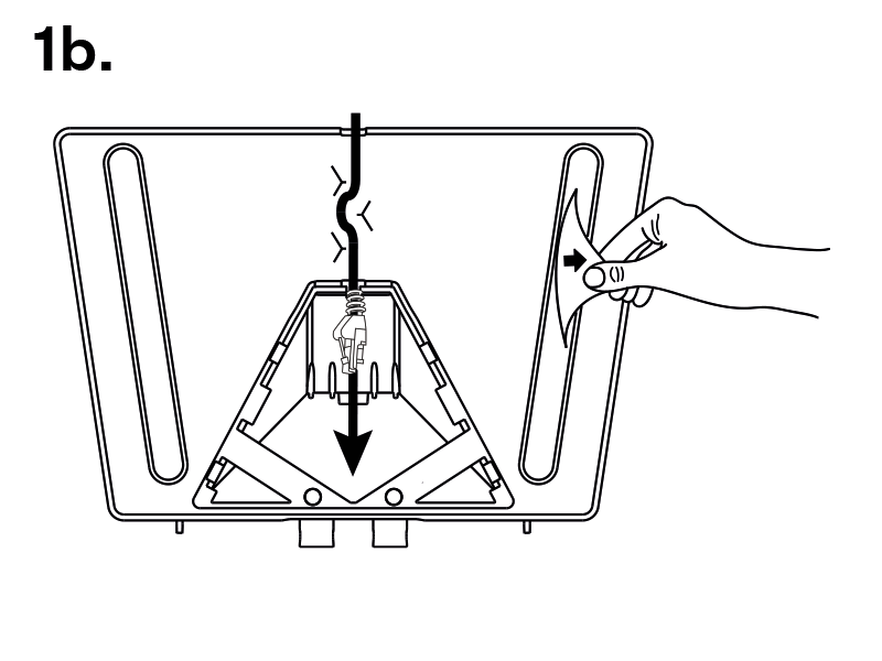
Having unpacked 2N® Clip, remove the metal holder for installation. Use both your hands at the same time to remove it safely. A careless removal and insufficient push might lead to a locking latch damage. Hence, follow the mentioned metal holder instructions below closely!
 |
- Push the locking latch in the center of the device bottom edge with your left hand in such a manner that it bends sufficiently for the metal holder removal. Do not push the locking latch from the top. You might get injured while removing the metal holder.
- Grasp the metal holder with your right hand and slide it downwards for removal.
 |
 |
 |
 |
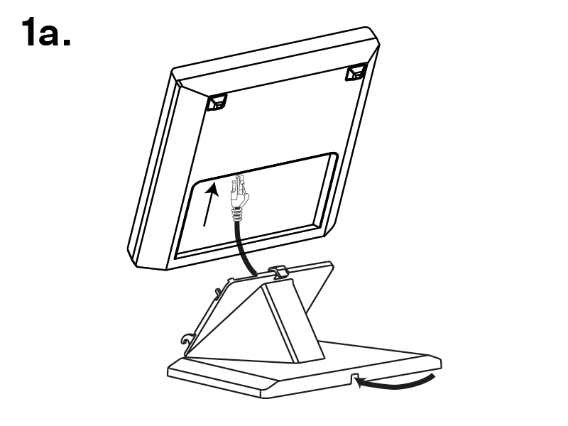
Draw the pre-prepared LAN connector through the stand bottom and connect it into the LAN connector socket. Place the cable into the pre-prepared groove in the center of the stand bottom. Unstick the protective foil from the stand antislip surfaces.
Caution
We recommend that you use a CAT5e UTP cable to fit the stand bottom groove size.
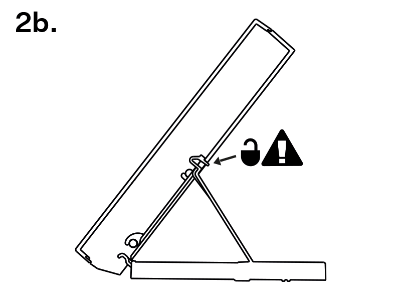
- Put the stand including the properly drawn and connected cable on the device. First snap in the stand hooks, then tilt the stand towards the device and lock the latch on the stand top edge into the device body.
Now the device is ready for basic operation. It is necessary to perform software configuration to achieve full functionality of the device.
To remove the device from the stand, reverse the steps - start by releasing the locking latch on the top edge of the stand.