Audio Sources
What you should know
- It is necessary to assign the created working source (SIP, playlist, microphone...) to a session in the Session menu to define where the contents should be played.
- 2N® Net Speaker supports several types of input sources for specific applications.
- The HW sources are based on the server PC sound card. External sound cards can be used too.
- 2N® Net Mic provides announcements to a session via button A if added to the Audio source for the particular session.
- 2N® Net Audio Encoder provides announcements if added to the Audio source for the particular session.
- In the event of button action (playing playlist to zone or live announcements to zone), 2N® Net Mic transmits with the highest priority.
- Click the preset 2N® Net Mic button and button A to generate the live announcement to zone action.
Explanatory notes for 2N® Net Mic buttons:
 ... A ... button for announcing
 ... B ... not supported in this version
 ... C ... function buttons 1–12 for playing playlist or making announcements to Zone/Net Audio Decoder/Net Speaker
Hardware Inputs
HW inputs are inputs of your server – PC on which the 2N® IP Audio Manager is running; refer to the system architecture in Introduction. A microphone, internal/external sound card and/or mixer are used for playing locally stored music using a standard audio player.
Playlists
A classic playlist creation principle is used like in common music players. Click the '+' button and add mp3, wma or wav files to create a new playlist. You can select more files than one (with Shift/Ctrl).
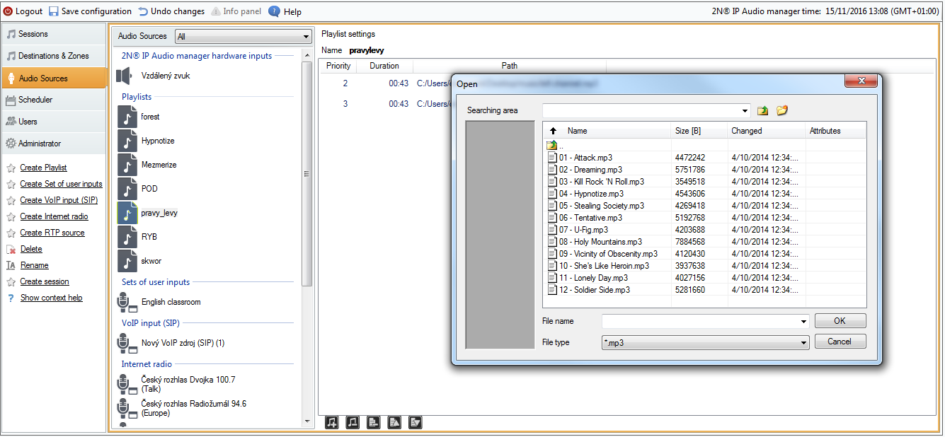 |
Adding Audio Files to Playlist
To add files to the new playlist from a PC other than that on which the server is running, use the Import file option in the Administration > File manager menu.
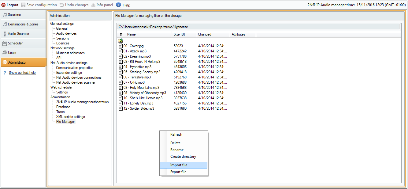 |
File Manager
In this way you can fill the server with mp3 files even remotely via the WAN.
Sets of User Inputs
Set of user inputs is a group of rules rather than an actual input. The rules define users with the right to use the input and also assign inputs to rooms if necessary.
Example: Suppose a language school has English and German classrooms. There are 4 teachers in the school: Mr. Cook, Ms. Scott, Hr. Himmel and Fr. Moselle. Use the set of user inputs to create English classroom input and German classroom input.
- Enable the "English classroom" virtual input for Mr. Cook and Ms. Scott.
- Enable the "German classroom" virtual input for Hr. Himmel and Fr. Moselle.
Doing this, you have created the possibility to play audio in the classrooms and let the teachers simply choose classrooms using the Console tool.
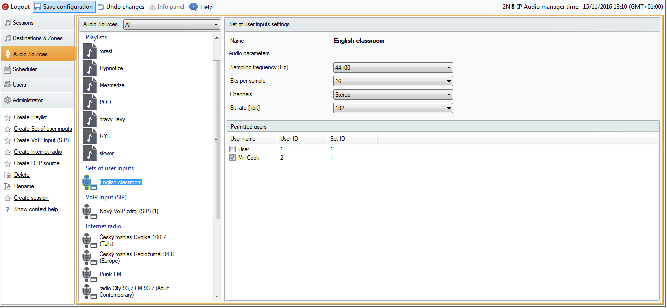 |
Adding English Teachers to Set of User Inputs
Internet Radio
The Internet radio source allows you to insert URI of the selected radio and set radio delay (in ms) – characterises the radio buffer size. The supported radio formats are mp3 and wma. In exceptional cases, the services providing internet radio management and playback may fail. For this reason, it is good to have a backup of at least one of the supported Internet radios from http://www.mikesradioworld.com/
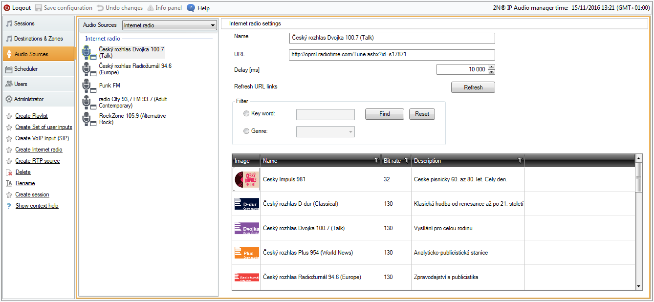 |
Internet Radio Parameters
User Input
User input is assigned to the user and defines the user audio stream parameters when playing from the Console is used, for example. The figure below shows the default input settings.
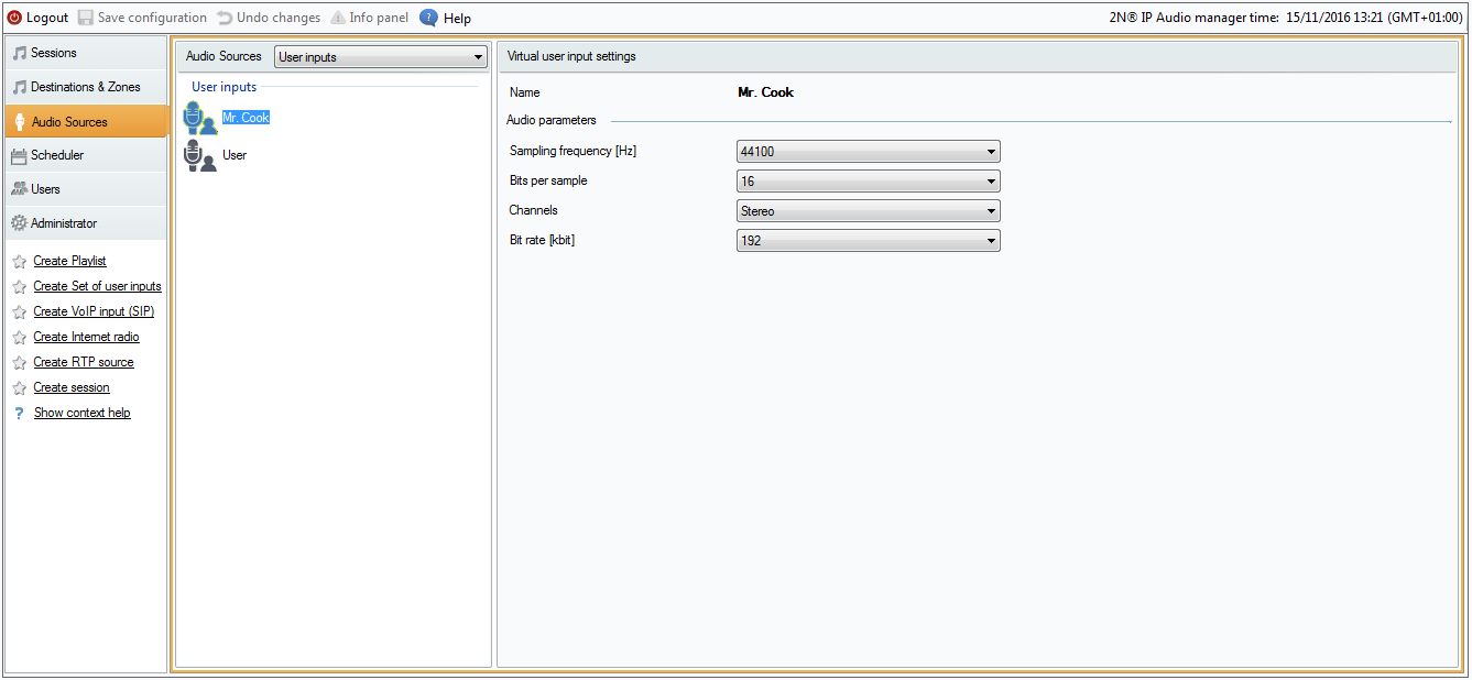 |
User Input Parameters
Generic RTP Input
Generic RTP input is a common audio input. All the devices that can transmit audio using RTP protocol and codec G711, L16 can serve as a sound source for the session. The sound source is defined by the listening port, the IP address (unless unicast, i.e. IP address of the server). If the 2N® IP Audio Manager listens on the defined multicast address, it is necessary to enter this address (then the specified port + IP multicast is considered). You can define the source IP address to make the sound source secure.
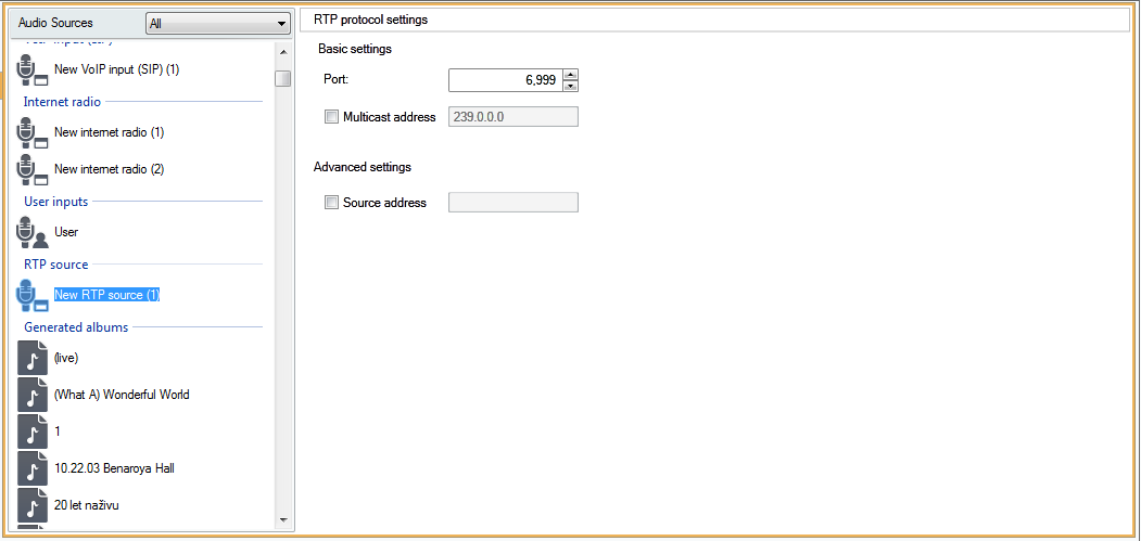 |
Generic RTP Input
Net Mic
2N® Net Mic is a hardware console with microphone, which enables you to make live announcements or broadcast pre-prepared files to different zones. You can define the audio path delay according to your network conditions to improve the communication quality.
To access 2N® Net Mic, click Audio Sources → Net Mic to display the 2N® Net Mic setting window.
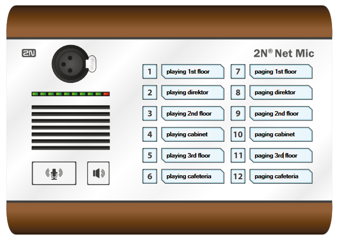 |
Initial View of 2N® Net Mic via 2N® IP Audio Control Panel
In the window above, set live announcements or playing files to 2N® Net Audio Decoder or 2N® Net Speaker to the 2N® Net Mic buttons. Click a number to set the function key.
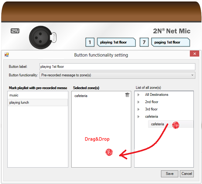 |
2N® Net Mic Button Function Setting
Select a playlist and drag it to the Selected zone to set Broadcasting to zone for the 2N® Net Mic button. Change the Button function item into Paging zone selection and drag the selected zone as mentioned above to assign live announcements to a zone. Now click Save and start using the 2N® Net Mic preset buttons.
Net Audio Encoder
Despite the gradual modernisation of audio systems to IP technology, customers are still encountering the need to connect an IP audio system to a traditional music sources such as FM radio stations, CD players or microphones. 2N® Net Audio Encoder can transfer traditional audio sources to IP technology and then ensure audio distribution over an IP network to various destinations. 2N® Net Audio Encoder provides announcements to the Session with logic input if 2N® Net Audio Encoder is added to the Audio source for this Session.
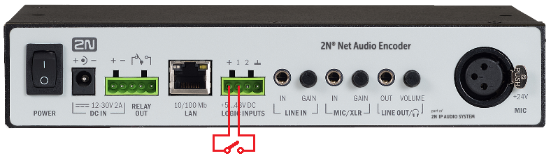
Logic input
Connecting the logic input of the 2N® Net Audio Encoder. There are two options how to control logic inputs. The first option is that you are connecting to the input labelled + (galvanically isolated +7 V supply) and the input labelled 1 (0 V). The other option is that the input responds to voltage and switches to the input labelled 1 (0 V) and GND.
A logic input can operate in both the latching and momentary states.
When a switch is used across the logic input, the stream is started by a brief ‘press and release’ and stopped by ‘press and release’ (latching). Alternatively, a constant press of the switch activates the stream and the stream is stopped upon release (momentary).
 |
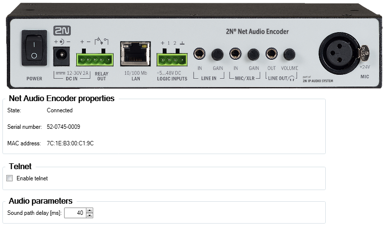 |
Initial View of 2N® Net Audio Encoder via 2N® IP Audio Control Panel
VoIP Input
The SIP source helps you connect 2N® Net Speaker to a VoIP (Voice over IP) PBX as a VoIP station via the SIP or a VoIP trunk. You have to know the PBX IP address, username and password (if requested) and the port to establish connection to the PBX. Refer to the subsections below for the parameters and setting options.
Another option is to allow direct VoIP calls to the 2N® IP Audio Manager by choosing Local SIP input. Then you have to assign the source to a session. Now the 2N® IP Audio Manager is able to receive direct VoIP calls from VoIP phones.
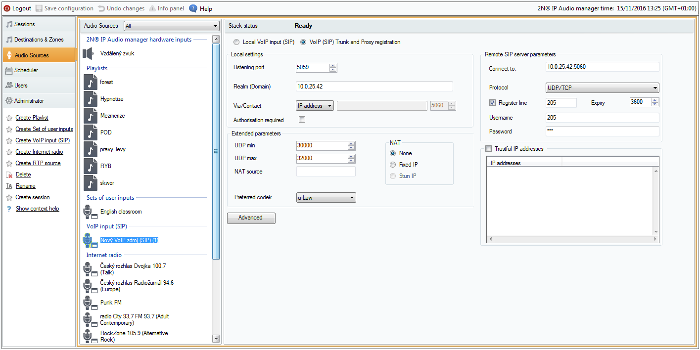 |
SIP Source Setting
Source Status
Refer to the upper menu section for information on the stack (communication protocol) type and current status.
- SOCK_TCP_ERROR – TCP socket failed to open.
- SOCK_UDP_ERROR – UDP socket failed to open.
- CREDS_IN_ERROR – authorisation server unavailable.
- CREDS_OUT_ERROR – authorisation client unavailable.
- REALM_CONFLICT – realm collides with another port's realm/alias.
- STUNNING – public address obtaining from STUN server in progress.
- STUN_TIMEOUT – STUN server inaccessible.
- EXPIRED – public address validity expired.
- SIP_REGISTERING – gateway registration in progress.
- REG_TIMEOUT – REGISTRAR server inaccessible.
- REG_NOT_AUTH – registration unauthorised.
- REG_REJECTED – registration rejected with error.
Local Settings
- Listening port – is a local port of the 2N® IP Audio Manager via which the given gateway is communicating with the counterparty.
- Realm (Domain) – define the domain over which this gateway is communicating. The domain and port specified here are relevant for subsequent call routing to the 2N® IP Audio Manager. The Request–URI field including Realm (Domain) + port are checked for incoming INVITE messages. If the values match the SIP GW setting, the packets are routed to the 2N® IP Audio Manager. The INVITE messages are served too whose Request–URI values are included in the Aliases field.
- Via/Contact header – define the contents of the Via and Contact headers. The following options are available:
- IP address – fill in the unique PBX IP address.
- FQDM – the header includes the PBX Host Name, which can be filled on the PBX IP interface.
- NAT – fill in the fixed public IP address and NAT port to which signalling messages for the PBX should be sent by the counterparty. Packets are routed to the PBX based on the set port routing IP address on the router.
- STUN – fill in the STUN server address and port to identify the current address behind the NAT router.
- Authorisation required – activate authorisation request for incoming calls from the counterparty. User login data are used for call authorisation. All logins are always searched through.
Remote SIP Server Parameters
- Connect to – set the IP address or DNS name of the counterparty (operator or another PBX) to which you want to connect the 2N® IP Audio Manager via a trunk (where call and registration requests shall be routed). To use a port other than 5060, specify the port behind the colon (192.168.122.43:5071).
- Protocol – specify whether UDP and/or TCP shall be used for transmission. If you choose NAPTR (Name Authority PoinTeR), a query to the DNS is made first and, depending on the reply, the proper transmission protocol is set. The Use DNS SRV parameter can be used with this setting and suitable DNS only.
- Register line – enable registration with the counterparty and specify the gateway registration number (Caller ID). No call setup requests can be resent to an unregistered gateway.
- Validity – set the registration validity term. The resultant value can be defined by the counterparty (if shorter).
Authorisation Data
- Name – user name for registration with the counterparty.
- Password – password for registration with the counterparty.
Trustful IP Addresses
The parameter helps secure the 2N® IP Audio Manager against undesired call attempts via the given SIP gateway. Tick off this option to make the PBX process only the requests coming from trustworthy IP addresses included in the list. Add, remove or modify an IP address to/in the list using the buttons to the right of the IP address list or the context menu retrieved in the IP address list with the right–hand mouse button.
SIP Parameters
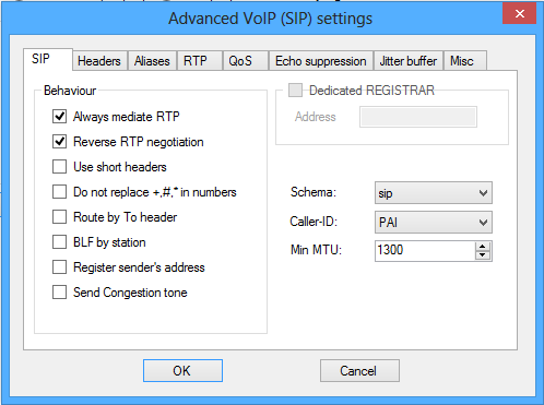 |
Advanced VoIP Settings
- Always mediate RTP – enable this parameter to route the RTP stream via the PBX VoIP card in all cases. Otherwise, the RTP stream might be routed outside the PBX (for VoIP – VoIP connections) and the PBX processes only signalling for such a call.
- Reverse RTP negotiation – tick off this option to set the codec negotiating method. If you do not tick off this option, the PBX offers codecs in the INVITE message.
- Use short headers – tick off this option to use abbreviated header items for outgoing SIP packets. Example: From = f, To = t, Via = v. This optimisation helps minimise data to be transmitted.
- Do not replace +,#,* in numbers – if you do not tick off this option, the above mentioned characters will be replaced with adequate strings %xx in numbers. Tick off the option to send the characters.
- Route by To header – if you tick off the option, incoming call routing on the port will obey the To header setting. Otherwise (and by default!), calls are routed by the Request URI header.
- Dedicated Registrar – is used for the gateway only and helps route registration to another server.
- Address – IP address of the selected Registrar server.
- Port – port of the selected Registrar server.
- Scheme – set the sip or tel scheme in the "To" and "From" headers of the SIP. tel is used for networks based on the numbering plan according to recommendation E.164.
- Min. MTU – set the minimum packet length for obligatory use of TCP in the UDP&TCP mode. The recommended maximum value is 1448 bytes.
Headers
- Complete domain – specify the domain to be used within the From and To headers.
- Send information – P-Asserted-Identity – activate the P-Asserted-Identity header for the INVITE message. This header is used for CLIR transmission to the counterparty, giving it information on the calling number even in the case of active CLIR (Calling Line Identification Restriction). By default, the header is enabled on the SIP Gateway and disabled on the SIP Proxy.
Aliases
Use this option to specify additional Realms (Domains) to be accepted on this port. Such incoming calls (their INVITEs) will be routed to this port whose Request–URIs match the given SIP GW or SIP Proxy settings and Domains or Aliases.
RTP
- DSP – here you can optimise data to be transmitted. Packets are not sent while the user is not speaking. VAD stands for Voice Activity Detection.
- Disabled VAD
- VAD acc. to G.729 Annex B
- VAD light
- Generate comfort noise – enable comfort noise generating. As users of classic analogue lines are used to some background noise, this option simulates a similar call impression to them.
- Mask lost packets – enable optimised computing of probable contents of lost packets.
QoS
The TOS/DiffServ section helps you set outgoing packet parameters which define the packet priority for processing by network elements.
- SIP – hexadecimal priority value for SIP packets.
- RTP – hexadecimal priority value for RTP packets.
- Default values – restore the default values for the two parameters.
Echo Suppression
Use this tab to activate various echo cancelling methods.
- Suppression disabled
- Profile G.168 8 ms
- Profile G.168 16 ms
- Profile G.168 32 ms
- Profile G.168 64 ms
- Profile G.168 128 ms
- Delay [ms]
- Adaptive suppression
- Non–linear processing
- Reuse of coefficients
- Automatic control
Jitter Buffer
Set the parameters in this tab to optimise packet delay fluctuation during network passage.
- Delay [ms]
- Depth [ms]
- Automatic adaptation
- Short adaptation parameters
- Low [ms]
- High [ms]
- Threshold
Miscellaneous
- Receive marks in call
- Mode – set the supported DTMF receiving mode for calls.
- Send marks by INFO method
- DTMF – select one of the two DTMF sending modes using the SIP INFO method. The modes have different formats of the DTMF transmitting message.
- KeepAlive
- Period – define the KeepAlive packet sending interval. The default value is 10s.
- STUN server – The STUN server helps NAT clients (i.e. PCs behind the firewall) set up telephone calls with the VoIP provider hosted outside the LAN.
- Address – complete the STUN server address (IP or domain name) to be used if the STUN IP method is selected in the port RTP interface configuration. The default value is stunserver.org.
- Port – set the port to be used for STUN. The default value is port 3478.
SD Card
Caution
- SD card is not included in the Sound sources that are managed by the Control Panel.
What you should know
- Make sure before inserting the SD card for the first time that the card has been formatted via the FAT32 file system.
- The violet LED flashes to signal SD card loading, the green LED flashes three times to signal successful loading and orange LED flashes three times to signal loading failure.
- Upon the first SD card insertion, four playlists (OFFLINE, USER0, USER1 and USER2 folders) and inifile (2NAudio.ini) are created.
- The playlist includes all .mp3 files from the folder, arranged alphabetically in English. All subfolders are also included alphabetically, i.e. following the files.
- Up to 4,000 files can be loaded.
- The OFFLINE playlist is used for SD card playing in the case of connection failure.
- The USER0 playlist is used for SD card playing when the logic input is activated.
- Press the button (logic input activation) to start playing and repress it to stop playing – you do not have to keep the button pressed to activate playing.
- Edit inifile to set the folders in greater detail.
Inifile
[OffLine] – parameters related to the given playlist
Folder – folder name
NowPlaying – currently played file
StartDelay – start delay (ms)
InterFileDelay – inter file delay (ms)
FromBegin – set 1 to play the playlist from the beginning
OneShot – set 1 to stop playing when the playlist is completed
WholeFile – stop playing after the current file is completed
[OffLine]
Folder=OFFLINE
NowPlaying=
StartDelay=0
InterFileDelay=0
FromBegin=0
OneShot=0
WholeFile=0

[User0]
Folder=USER0
NowPlaying=
StartDelay=0
InterFileDelay=0
FromBegin=0
OneShot=0
WholeFile=0

[User1]
Folder=USER1
NowPlaying=
StartDelay=0
InterFileDelay=0
FromBegin=0
OneShot=0
WholeFile=0

[User2]
Folder=USER2
NowPlaying=
StartDelay=0
InterFileDelay=0
FromBegin=0
OneShot=0
WholeFile=0