5.2.1 Users
 |
The Users list contains up to 10 000 users (variable in the 2N IP intercom models). Also includes the users that can be called via the quick dial buttons and the users that are assigned the RFID card, code, etc. access to the building.
If your external card reader is connected to the intercom via the Wiegand interface, the card ID is shortened to 6 or 8 characters for transmission (depending on the transmission parameters). If you apply a card to the reader, you will receive a complete ID, which is typically longer (8 chars or more). The last 6 or 8 characters, however, are identical. This is useful for comparing card IDs with the intercom database: if the IDs to be compared have different lengths, they are compared from the end and match has to be found in 6 characters at least. If they have identical lengths, all the characters are compared. This ensures mutual compatibility of the internal and external readers.
All cards applied via the reader or the Wiegand interface are recorded. Refer to the Status / Access Log menu for the last 10 cards including the card ID/type, card tapping time and other information if necessary. With small systems, you can make a trick to enter card IDs: tap the card on the intercom reader and find it in the Access Log. Double-click to select the card ID and push CTRL+C. Now that you have the card ID in your box, you can insert it with CTRL+V in any intercom setting field.
Having been read, the card ID is compared with the intercom card database. If the card ID matches any of the cards in the database, the appropriate action will be executed: switch activation (door unlocking, etc.). To change the switch number to be activated, use the Associated Switch parameter in the Hardware / Card Reader menu (2N IP Base, Vario, Force, Safety models) or the Associated Switch parameter in the Hardware / Modules menu of the card reader module (2N IP Style, 2N IP Verso model).
Use the Hardware / Buttons menu to assign the quick dial users. You can change the user and button settings as necessary. Most of the 2N IP intercoms are equipped with one or more quick dial buttons. Refer to the Installation Manual of your intercom model for the quick dial button count and extending options.
Warning
- You are not advised to edit the device directory that is managed by 2N Access Commander via the device web interface. Due to synchronization with 2N Access Commander the directory changes made via the web interface will be lost.
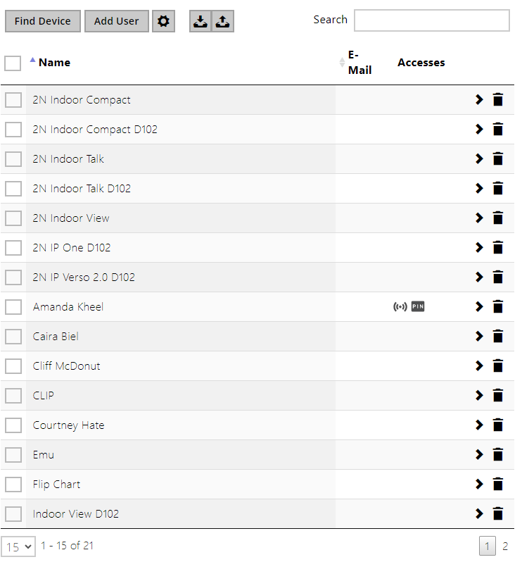 |
 icons in the access column describe the active user authentications. The user's position in the list is sorted alphabetically.
Every record in the Users list includes the following parameters:
|
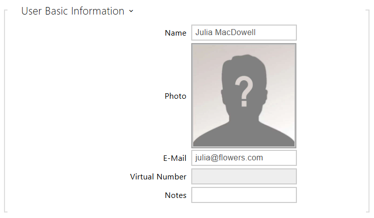
- Name – mandatory parameter for easier user search, for example.
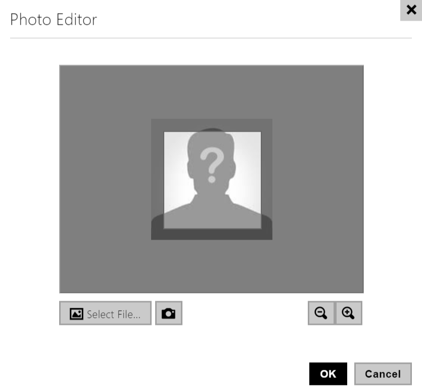
- Photo – load the user photo. Click the photo adding frame to display the Photo editor to load a photo from a file or create a user photo using an integrated camera. The supported photo formats are .jpg, .png and .bmp. This function is only available in display-equipped models: 2N IP Style, 2N IP Verso and 2N IP Vario.
 |
Caution
- If the cropped image does not fill the whole crop window space, the resultant picture is centered on 2N IP Style.
- E-Mail – user e-mail address for sending missed call information. You can enter more e-mail addresses separated with commas.
Virtual Number – you can use the virtual number for calling a user via the numeric keypad on the device. The virtual number can have 1 to 7 places. The first/last place can be either a digit or a letter, the remaining positions can only be digits (A123, 456B, C12E, e.g.). Virtual numbers can be set according to apartment numbers, for example. Virtual numbers are especially convenient for installations where the speed dial buttons are insufficient. Not being related to the actual user phone numbers, virtual numbers help protect the user phone numbers on the device.
Caution
Enable Calling to Virtual Numbers in Calling > General settings > Outgoing calls.
Note
- Enter the user virtual number via the keypad and press an asterisk (*) or the call button (earpiece icon) to start a call.
Notes – used for adding custom notes to a contact. It is possible to enter metadata into the note that is used for third-party system integrations. You can work with the content of the note in the Comparator block in Automation, see 2N Automation Manual.
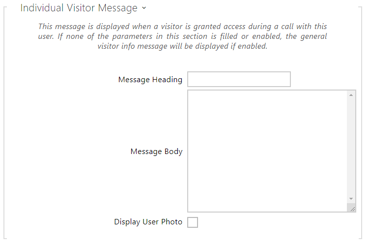 |
An individual visitor message is shown on the 2N IP Style display when this particular user grants the visitor access to the device during a call. A visitor is the person that started a call to this user from the device.
If none of the parameters in this section is completed/enabled, a general visitor information message is displayed if enabled; refer to 5.2.4 Info Messages.
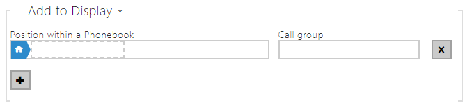 |
- Position within a Phonebook – the root directory is only created by default, to which users from the directory can be added directly. The root directory cannot be deleted or renamed. One user can be assigned to up to 5 root directory subgroups.
- Call Group – enter a user group name to be displayed in the directory. By dialing the group you make calls to all of its users at the same time. When one call is answered, the other calls will be terminated automatically.
Caution
- The <, > and / characters are not allowed for the Name, Position within a Phonebook and Call group parameters.
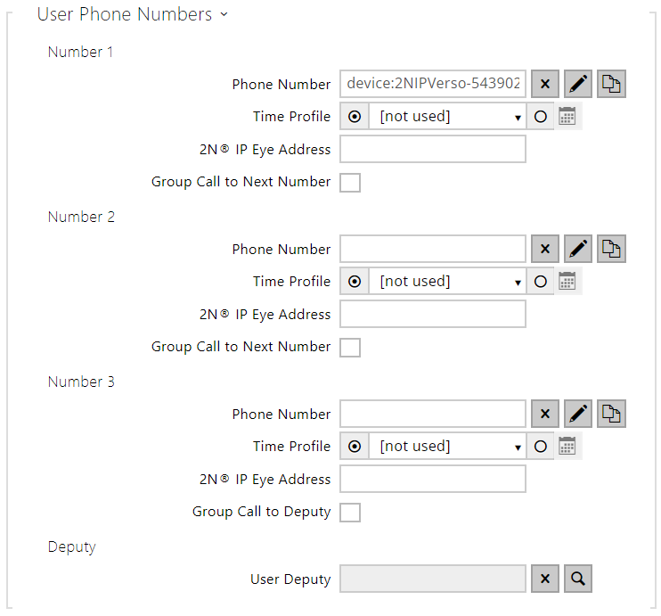 |
Phone Number – enter the phone number of the station to which the call shall be routed. Enter the address sip:[user_id@]domain[:port] for Direct SIP calling, e.g.: sip:200@192.168.22.15 or sip:name@yourcompany. For local calls to the 2N IP intercoms and answering units enter device:device ID. Set the device name in the respective devices. For calls to Crestron enter RAVA:device_name. Enter /1 or /2 behind the phone number to specify which SIP account shall be used for outgoing calls (account 1 or 2). Enter /S or /N to force an encrypted or unencrypted call respectively. Enter /B to activate door opening via Callback. Combine account selection, encryption and Callback door opening by e.g. /1S, /1B. etc. The parameter can contain up to 255 characters.
Click to edit the phone number details.
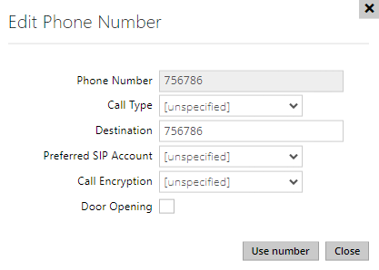
Call Type – set the scheme in the called destination URI. If you choose Without scheme ([unspecified]), the URI is completed with the data from the SIP account settings. Further settings include direct SIP calls (sip:), 2N local calls (device:), Crestron calls (rava:), connections to MS Teams accounts (msteams:) or calls with VMS, e.g. AXIS Camera Station (vms:).
Destination – Set the other parts of the called destination URI. As a rule, it contains the number, IP address, domain, port or device identifier. Enter an asterisk (*) for calls to the VMS.
Preferred SIP Account – SIP account 1 or 2 is primarily used for calling.
Call Encryption – set mandatory call encryption or no encryption.
Door Opening – via callbacks.
- Time Profile – assign a time profile to each phone number to define the number validity. If the profile in inactive, the phone number is not used and the following phone number is dialed if defined.
- IP® Eye Address – set the address of the PC to be sent a special UDP message on each active user phone number call. With the aid of this message, the 2N IP Eye application displays the camera image screen for those users who are not provided with a display-equipped videophone. Enter the address as follows: domain[:port1][:port2], e.g.: computer.yourcompany.com or 192.168.22.111. The port1 and port2 parameters are optional and are used in case there is Network Address Translation (NAT) between the PC and intercom and the addresses have to comply with the router or another NAT-executing device. The port1 (default value: 8003) parameter defines the destination port for the UDP messages sent to 2N IP Eye. The port2 (default value: 80) parameter defines the destination port for the 2N IP Eye – intercom HTTP communication.
Note
- The 'IP Eye Address' function is available in selected 2N IP intercom models only (refer to the model and license overview).
- When Enhanced Integration is not licensed on a device, it is possible to control the locks only when a call is in progress. If a call with user, who has 2N IP Eye address filled in, is in progress, no license is needed to control the locks.
Tip
Tip
- Video Tutorial: SW application for IP intercoms – 2N IP Eye
- Parallel Call to Following Number – enable group calling, i.e. calling to more phone numbers at the same time. You can call the first two numbers, the last two numbers, or all of the three user numbers in parallel. Answering one call automatically terminates the other calls.
- Parallel Call to Following Deputy – enable group calling, i.e. calling to more phone numbers at the same time. You can call the first two numbers, the last two numbers or all of the three user numbers in parallel. Once one of the calls is answered, the other calls are automatically terminated. The maximum total count of numbers to be dialed in parallel is 16, which can occur when group calling and multiple numbers assigned to a speed dial button are used simultaneously.
- User Deputy – select a user to which the user calls will be routed in the event of inaccessibility. Enter the user position number or use the search button. The maximum total count of calls to be dialed in parallel is 16, which can occur when group calling and multiple numbers assigned to a speed dial button are used simultaneously.
Note
- The User Deputy function is available in selected 2N IP intercom models only (refer to the model and license overview).
|
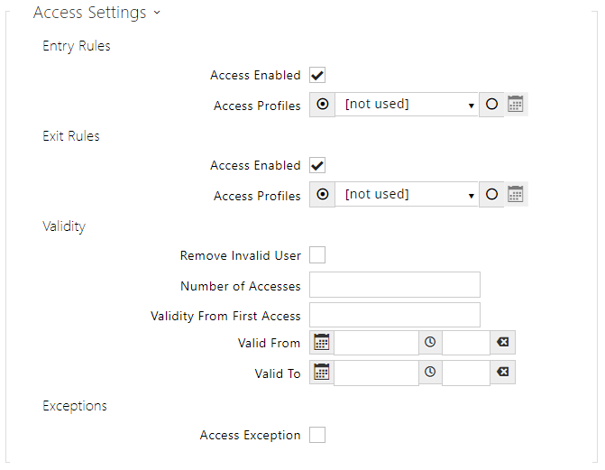
- Entry Rules
- Access Enabled – enable authentication via this access point.
- Access Profiles – select one of the profiles pre-defined in Directory / Time profiles or set the time profile for this element manually.
- Exit Rules
- Access Enabled – enable authentication via this access point.
- Access Profiles – select one of the profiles pre-defined in Directory / Time profiles or set the time profile for this element manually.
- Validity
- – set the time that the user will be valid for from the first successful authorization. Leave empty for no relative validity period. Relative validity may shorten the validity period but never extend it. The time is set in the format HH:MM, e.g., 06:09.
- Valid from – set the beginning of the mode validity term. Leave empty so that the start is not restricted. Valid From must precede Valid To.
- Valid to – set the end of the mode validity term. Leave empty so that the end is not restricted. Valid To must be after Valid From.
- Access Exception – enable this user to bypass Access Blocking and Anti-Passback rules.
 |
Caution
- If the codes are identical with the codes already defined in the intercom configuration, the
 mark will appear at the colliding codes.
 - The initial zeros are ignored as far as the code uniqueness is concerned. This means that two codes ONLY differing by the initial zero count are considered identical.
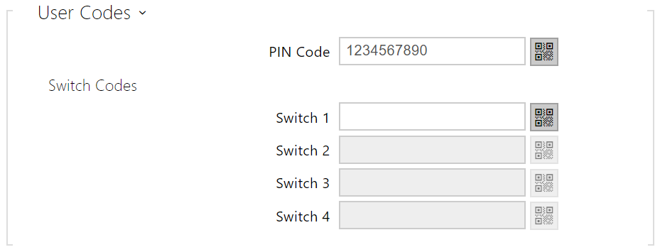
- PIN Code – set the user's Personal Identification Number. The code must include 2 characters at least.
 – generate a QR code image. Codes shorter than 4 digits cannot be entered by QR code reading for security reasons. The codes must contain digits only. If authentication using a hexadecimal QR code is required, convert this code into the hexadecimal format before entering. Accepted hexadecimal range: 1000 to FFFF FFFF FFFF.
- Switch 1–4 – set a private user switch activation code: up to 16 characters including digits 0–9 only. The code must include 2 characters at least. The code must include at least two door unlocking characters via the intercom keypad and at least one door unlocking character via DTMF.
- – generate a QR code image. Codes shorter than 4 digits cannot be entered by QR code reading for security reasons. The codes must contain digits only. If authentication using a hexadecimal QR code is required, convert this code into the hexadecimal format before entering. Accepted hexadecimal range: 1000 to FFFFFFFF.
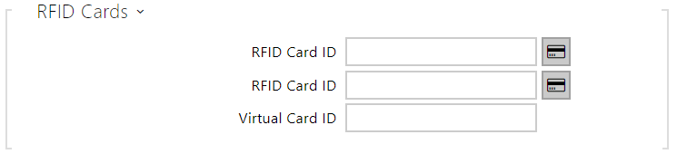 |
- RFID Card ID – set the user access card ID: 6–32 characters including 0–9, A–F. Each user can be assigned up to two access cards. When a valid card is tapped on the reader, the switch associated with the card reader gets activated. If the double authentication mode is enabled, the switch can only be activated using both a card and numeric code.
- Virtual Card ID – set the user virtual card ID for user identification in the devices that are integrated with the 2N IP intercoms via a Wiegand interface. Each user can be assigned just one virtual card. The virtual card ID is a sequence of 6–32 characters: 0–9, A–F. After the user is validated via the Bluetooth/biometric reader, the identifier is sent to the device integrated with the 2N IP intercom via Wiegand.
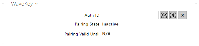 |
- Auth ID – unique WaveKey ID for access control. It's saved to the mobile device during the pairing process. The Auth ID consists of 32 hexadecimal characters.
 pair via USB reader
 pair via this device
 delete Auth ID
Pairing State – display the current pairing state (Inactive, Waiting for pairing, PIN validity expired, Paired, Too many attempts).
Note
- After 10 unsuccessful pairing attempts, a 30 s pause is activated automatically for security reasons, during which it is impossible to make any further pairing attempts.
- Valid Until – date and time at which the authorization PIN validity expires or the temporary pairing suspension ends.
Pairing via Bluetooth Module in Intercom
To pair a mobile phone with the user:
- Click
 at Auth ID to start pairing for the selected user account.
 - A dialogue window with the PIN code is displayed.
- Find the appropriate reader in the My2N application and press Start pairing.
- Enter the code from item 2 into the input field.
- Pairing is completed.
Refer to 5.4.2 Access Control for My2N configuration details.
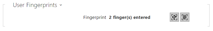 |
- User Fingerprints – display the set count of fingerprints; up to 2 different fingerprints can be set. This section is displayed only if the biometric reader module is available.
 enroll via USB reader.
 enroll via Fingerprint scanner module 3.
Caution
- The fingerprint loading capacity is up to 2000 per device.
Refer to Subs. 5.2.1.1 User Fingerprint Setting Instructions for user fingerprint loading details.
 |
In case the function is on, the event is recorded into the LicensePlateRecognized history when a valid HTTP request has been received.
If an image is sent within the HTTP request (photo part or whole photo of the license plate detecting scene), it is saved. The last five photos are stored in the device memory and can be retrieved via an HTTP request sent to api/lpr/image available in 2N Access Commander.
It is advisable that each license plate should be assigned to just one entry in the directory. Multiple license plate assignments may result in the inability to assign a license plate to an entry in the directory unambiguously (the first entry assigned the specified license plate is selected and given the access rights).
- License Plates – set the car license plates for the selected entry in the directory. An entry can be assigned multiple license plates separated with commas (up to 20). The set license plates are used for recognizing license plates from external camera images (refer to the Interoperability Manual for details). One license plate may include up to 10 characters. The set string length is limited to 255 characters.
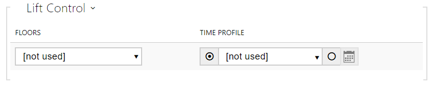 |
- Floors – select the floors available to the user.
- Time Profile – select one or more time profiles to be applied. Set the time profiles in the Directory / Time Profiles section.
 mark the selection from predefined profiles or manual setting of a time profile for the given element.
 set a time profile for the given element.